HONEYWELL UNITARY CONTROLLER - 230 VAC - INSTALLATION INSTRUCTIONS
31-00610-01 12
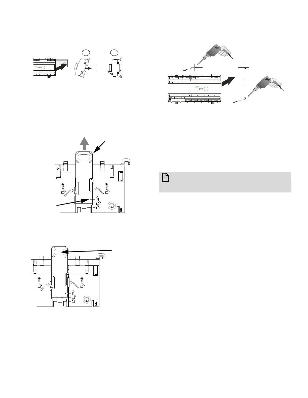
3. Hold the controller as shown in below image and
Mount the controller onto the DIN rail.
Fig. 8 Controller mounting on DIN Rail
Wall Mounting
1. Extend all red clips to the screw mounting position
by inserting the flat blade screwdriver at a marked
location and move up the nod from the lower slot
to the upper slot as shown in figure 9.
Fig. 9 Screw Mounting Position
2. Hold the controller along the wall and mark drilling
locations through the screw red clip slots, as
shown in figure 10.
Fig. 10 Drill mark location
3. Remove the controller from the wall and drill four
holes at the marked locations.
Fig. 11 Mounting and Dismounting
4. Insert anchors into the four mounting screw holes.
5. Place the controller on the wall/panel so that the
holes are aligned. Insert the screws into the top-
side holes first and fasten them with a screwdriver.
6. Insert the screws into the bottom hole and fasten
them with a screwdriver.
NOTE:
It is recommended to use the 6/18 1-inch pan
head Phillips tapping screws.
O1
C IO2 IO3 C IO4 IO5 C IO6 IO7 C IO8
C IO9 C IO11 C IO12
IO
52
53 55 56 57 58 59 61 62 63 65 66 67 68 69 71 7254 6 7
24VDC
OUT
UIO
IO13 C IO14IO15 C IO16
32 33 34 35 36 37 38
CO3 CO4C
01
18
52
53 55 56 57 58 59 61 62 63 65 66 67 68 69 71 7254 6 7
32 33 34 35 36 37 38
18
Drill mark
4.8 inches
(121.6 mm)
Large: 6.3 inches (160 mm)
Small: 4.5 inches (110 mm)
RS485
1
+
-
WM1 / 2
IO1 C IO2 IO3 C IO4 IO5 C IO6 IO7 C IO8
C IO9 C IO11 C IO12
COM
RS485 1 SYLK UIO
24VDC
OUT
24VDC
OUT
IO1
POWER 230V
NC1NO1 IN1 NC2 NO2 IN2
NC3NO3 IN3 NC4 NO4 IN4
DO RELAY
644645 47 48 49 50 51 52 53 55 56 57 58 59 61 62 63 65 66 67 68 69 71 7254 6 7
4321 56789 11121314151
24VDC
OUT
UIO
IO13 C IO14IO15 C IO16
32 33 34 35 36 37 38
PORT1 PORT2
10/100 SWITCHED
DO CHP
CO3 CO4CCO1 CO2C
18 19 21 22 232
644645 47 48 49 50 51 52 53 55 56 57 58 59 61 62 63 65 66 67 68 69 71 7254 6 7
4321 56789 11121314151 32 33 34 35 36 37 38
18 19 21 22 232
N
L
V
RS485 1
POW24
 Loading...