HONEYWELL UNITARY CONTROLLER - 230 VAC - INSTALLATION INSTRUCTIONS
31-00610-01 8
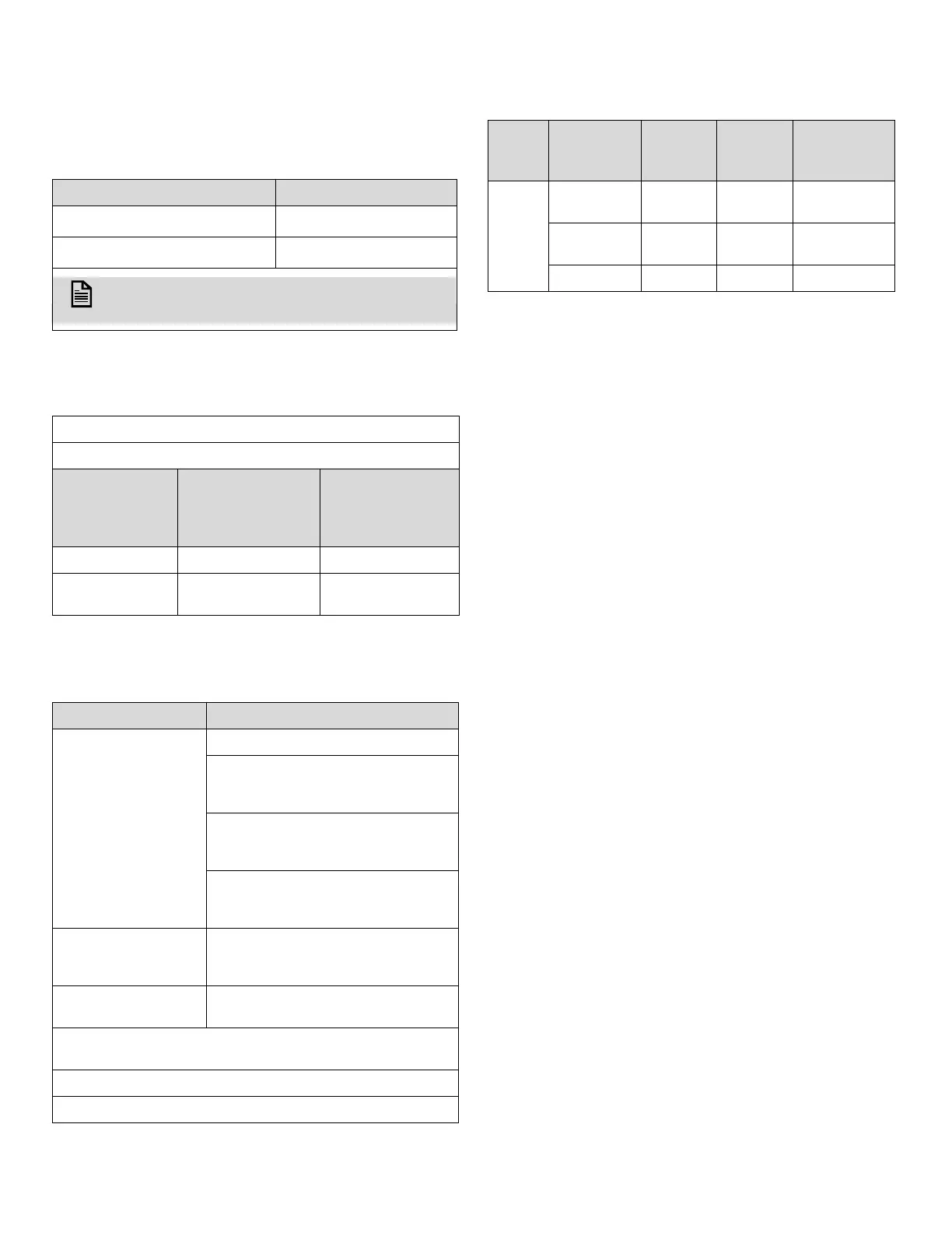
Wire Gauge Range
Table 11 Wire Gauge Range
Chopper Output (CHP)
Relays
Table 14 Fuse for Relays
Parameter Specification
Chopper/Auxiliary output
26-18 AWG
Relay
18-14 AWG
NOTE:
The range will depend on the current supplied.
Table 12 Chopper Output (CHP)
Chopper works with maximum 24 VAC, 50/60 Hz
Type 1
Ambient
temperature
Constant
current shared
across all 4
outputs
Inrush current
for 0.1 sec
shared across
all 4 outputs
Up to 50 °C 1.5 A 3.5 A
Between 50 °C
and 65 °C
0.6 A 3.5 A
Table 13 Relays
Parameter Specification
Contact Rating
Up to 240/277 VAC or 24 VDC
3 contacts per relay (Normally
open (NO), Normally closed (NC),
Common (IN)).
10 A constant current on
normally open contact and 100 A
inrush for 100 ms.
Total current across all relays is
limited to 12 A if all commons are
connected via a relay jumper.
Output
240/277 VAC, 50/60 Hz, or 24
VDC, 12 A Max. total common
(10 A Max. per Relay)
Number of
Automatic Cycles
40000 cycles for contact A (NO)
6000 cycles for contact C (CO)
Type of disconnection or interruption provided by each
circuit
Relay outputs can be used as dry contact output.
Type 1.C
Input
Fuse Part
Number
Current
Rate
[A]
Voltage
Rate
[A]
Holder
Part
Number
Relay
021812.5
MXP
12.5 250 01500520H
0505012.
MXP
12 250 150603
FCD-12.5A 12 250 01500520H
 Loading...