HONEYWELL UNITARY CONTROLLER - 230 VAC - INSTALLATION INSTRUCTIONS
31-00610-01 18
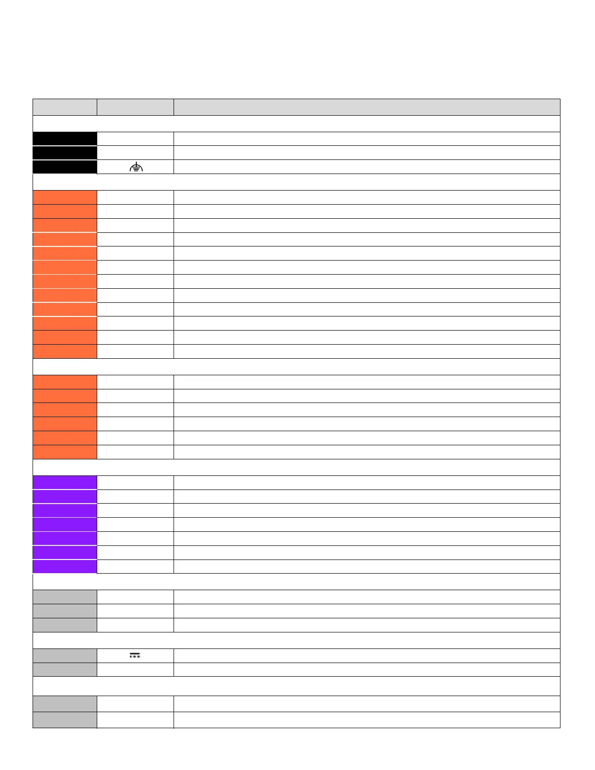
Terminal Connections
Table 15 Terminal Connections
Terminal Label Description
Power 230 V
1 L
2 N Neutral
3 Earth ground (connected to building earth ground)
DO Relay
4 NC1 Normally Closed 1
5 NO1 Normally Open 1
6 IN1 Universal signal input / output 1
7 NC2 Normally Closed 2
8 NO2 Normally Open 2
9 IN2 Universal signal input / output 2
10 NC3 Normally Closed 3
11 NO3 Normally Open 3
12 IN3 Universal signal input / output 3
13 NC4 Normally Closed 4
14 NO4 Normally Open 4
15 IN4 Universal signal input / output 4
DO CHP
18 CO1 CO1 chopper output
19 C Common
20 CO2 CO2 chopper output
21 CO3 CO3 chopper output
22 C Common
23 CO4 CO4 chopper output
UIO
32 IO13 Universal signal input / output 13
33 C Common
34 IO14 Universal signal input / output 14
35 IO15 Universal signal input / output 15
36 C Common
37 IO16 Universal signal input / output 16
38 24 VDC OUT Power Output
RS485 - 1
45 + RS-485 bus + (for Modbus only)
46 - RS-485 bus - (for Modbus only)
47 COM Common
Power 24
48 Power supply voltage (connected to 24 VDC)
49 V0 Power supply voltage (connected to 24 V0)
SYLK
TM
50 +
Sylk
TM
Bus
51 -
Sylk
TM
Bus
 Loading...