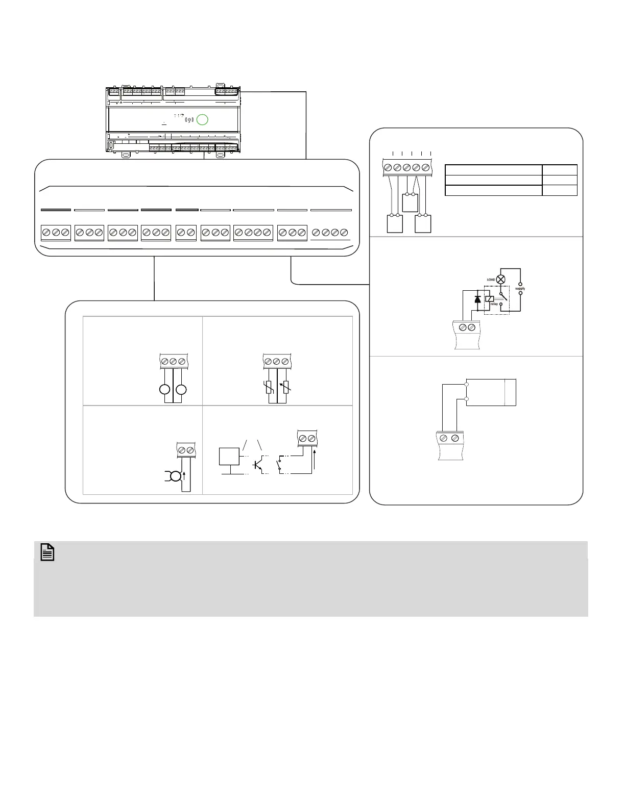
Fig. 16 Universal IO Wiring Examples
room.
wrong direction.
RS485
1
+
-
WM1 / 2
IO1 C IO2 IO3 C IO4 IO5 C IO6 IO7 C IO8
C IO9 C IO11 C IO12
COM
RS485 1 SYLK UIO
24VDC
OUT
24VDC
OUT
IO1
POWER 230V
NC1NO1 IN1 NC2 NO2 IN2
NC3 NO3 IN3 NC4 NO4 IN4
DO RELAY
644645 47 48 49 50 51 52 53 55 56 57 58 59 61 62 63 65 66 67 68 69 71 7254 6 7
4321 56789 11121314151
24VDC
OUT
UIO
IO13 C IO14IO15 C IO16
32 33 34 35 36 37 38
PORT1 PORT2
10/100 SWITCHED
DO CHP
CO3 CO4CCO1 CO2C
18 19 21 22 232
644645 47 48 49 50 51 52 53 55 56 57 58 59 61 62 63 65 66 67 68 69 71 7254 6 7
4321 56789 11121314151 32 33 34 35 36 37 38
18 19 21 22 232
N
L
V
RS485 1
POW24
Output Connection Example
Input Connection Example
+
-
0 to 10 VDC
V
Voltage Inputs
Thermistor / Resistive input
Volt-free / Digital input
Current Input
100 to
100
:
volt free
contact
open
collector
Ensure correct
polarity
logic
circuit
TTL /
CMOS
0V
IOx
C
+
-
V
V
IOx
IOx
C
S
External
Power
Supply
Ensure correct
polar
ity
SSS
S
0V IN
IN 0V
0V
IN
Output Type Load
0 to 10 VDC, 10 mA max.
1k :
4 to 20 mA
550:
IOx
C
IOx
IOx
C
Externally Powered
C
IOx
- Voltage output to power external relay
- Protective Diode is recommended
to protect the output
+
-
Ensure correct
polarity
IOx
C
0 to 10 V
LOAD
Ensure correct
polarity
Analog Output (UIO)
+
-
IOx
C
Analog Output (UIO) provides a variable
voltage between 0-10 VDC and the
output can source up to 20mA
52
53
54
IO1
C
IO2
16 x Universal Input/Output (UIO)
55
56
57
IO3
C
IO4
58
59
60
IO5
C
IO6
61
62
63
IO7
C
IO8
66
67
68
IO9
C
IO10
69
70
71
IO11
C
IO12
32
33
34
IO13
C
IO14
35
36
37
IO15
C
IO16
38
24 VDC
OUT
72
24 VDC
OUT
64
65
C
24 VDC
OUT
Ensure correct
polarity
wetting
current
3.5 mA
e.g, 20 k NTC
PT 1000
K
IOx
C
IOx
 Loading...