95
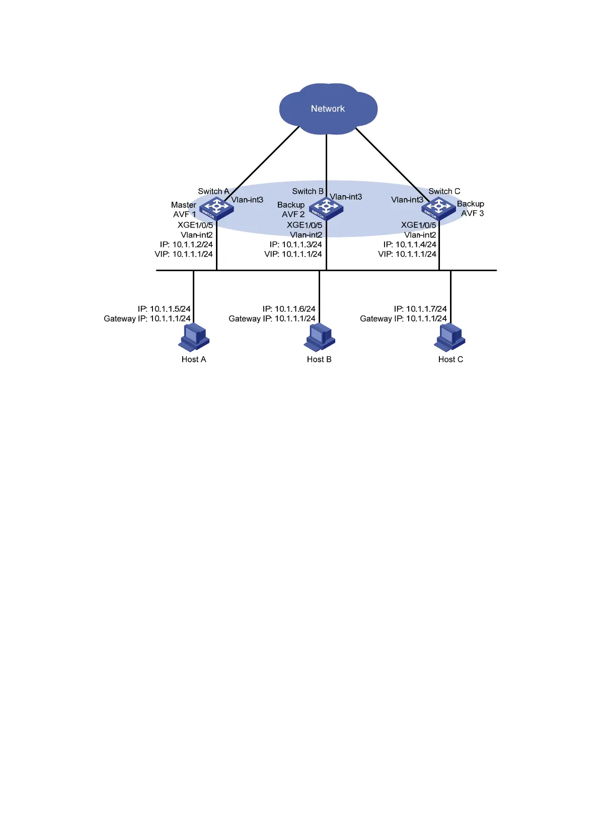
Figure 28 Network diagram
Configuration procedure
1. Configure Switch A:
# Configure VLAN 2.
<SwitchA> system-view
[SwitchA] vlan 2
[SwitchA-vlan2] port ten-gigabitethernet 1/0/5
[SwitchA-vlan2] quit
# Configure VRRP to operate in load balancing mode.
[SwitchA] vrrp mode load-balance
# Create VRRP group 1, and set its virtual IP address to 10.1.1.1.
[SwitchA] interface vlan-interface 2
[SwitchA-Vlan-interface2] ip address 10.1.1.2 24
[SwitchA-Vlan-interface2] vrrp vrid 1 virtual-ip 10.1.1.1
# Assign Switch A the highest priority in VRRP group 1, so Switch A can become the master.
[SwitchA-Vlan-interface2] vrrp vrid 1 priority 120
# Configure Switch A to operate in preemptive mode, so it can become the master whenever it
operates correctly. Set the preemption delay to 5 seconds to avoid frequent status switchover.
[SwitchA-Vlan-interface2] vrrp vrid 1 preempt-mode delay 5
[SwitchA-Vlan-interface2] quit
# Create track entry 1 to monitor the upstream link status of VLAN-interface 3. When the upstream
link fails, the track entry transits to Negative.
[SwitchA] track 1 interface vlan-interface 3
# Configure the VFs in VRRP group 1 to monitor track entry 1, and decrease their weights by 250
when the track entry transits to Negative.

 Loading...


