65
Monitor Link configuration example
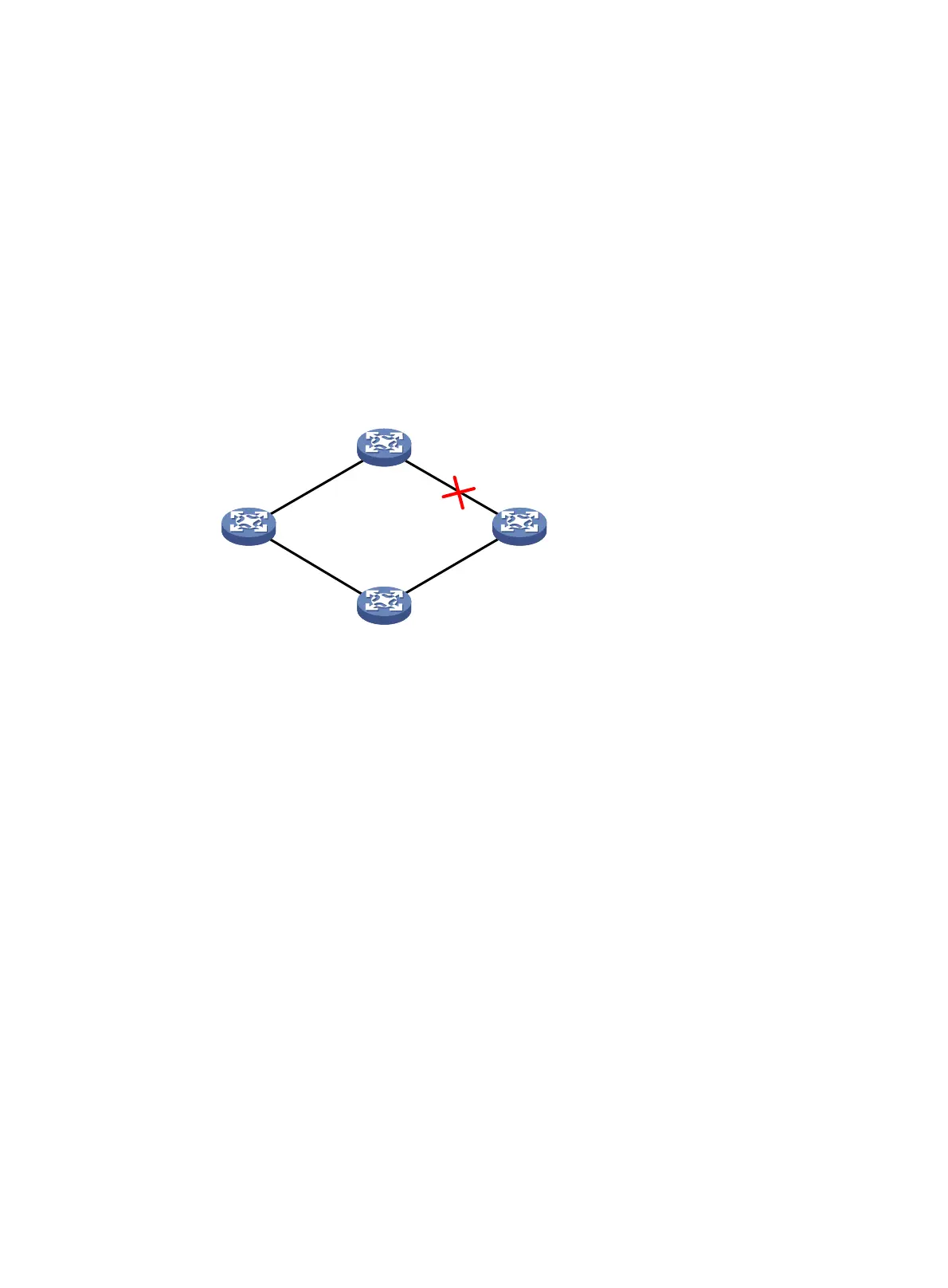
Network requirements
As shown in Figure 17:
• Device C is a Smart Link device, and Device A, Device B, and Device D are associated devices.
Traffic of VLANs 1 through 30 on Device C is dual-uplinked to Device A through a smart link group.
• Implement dual uplink backup on Device C. When the link between Device A and Device B (or
Device D) fails, Device C can detect the link fault and perform uplink switchover in the smart link
group.
For more information about Smart Link, see "Configuring Smart Link."
Figure 17 Network diagram
Configuration procedure
1. Configure Device C:
# Create VLANs 1 through 30.
<DeviceC> system-view
[DeviceC] vlan 1 to 30
# Map these VLANs to MSTI 1.
[DeviceC] stp region-configuration
[DeviceC-mst-region] instance 1 vlan 1 to 30
# Activate MST region configuration.
[DeviceC-mst-region] active region-configuration
[DeviceC-mst-region] quit
# Shut down Ten-GigabitEthernet 1/0/1.
[DeviceC] interface ten-gigabitethernet 1/0/1
[DeviceC-Ten-GigabitEthernet1/0/1] shutdown
# Disable the spanning tree feature on the interface.
[DeviceC-Ten-GigabitEthernet1/0/1] undo stp enable
# Configure the interface as a trunk port.
[DeviceC-Ten-GigabitEthernet1/0/1] port link-type trunk
# Assign the interface to VLANs 1 through 30.
[DeviceC-Ten-GigabitEthernet1/0/1] port trunk permit vlan 1 to 30
Device A
Device DDevice B
X
GE
1
/
0
/
1
X
GE
1
/
0
/
2
X
G
E
1
/
0
/
1
X
G
E
1
/
0
/
1
X
G
E
1
/
0
/
2
X
G
E
1
/
0
/
2
Device C
X
G
E
1
/
0
/
1
X
G
E
1
/
0
/
2

 Loading...


