52
Protected VLAN : Reference Instance 1
Member Role State Flush-count Last-flush-time
-----------------------------------------------------------------------------
XGE1/0/1 PRIMARY ACTIVE 5 16:45:20 2012/04/21
XGE1/0/2 SECONDARY STANDBY 1 16:37:20 2012/04/21
Use the display smart-link flush command to display the flush messages received on a device.
# Display the flush messages received on Device B.
[DeviceB] display smart-link flush
Received flush packets : 5
Receiving interface of the last flush packet : Ten-GigabitEthernet1/0/3
Receiving time of the last flush packet : 16:50:21 2012/04/21
Device ID of the last flush packet : 000f-e23d-5af0
Control VLAN of the last flush packet : 10
Multiple smart link groups load sharing configuration example
Network requirements
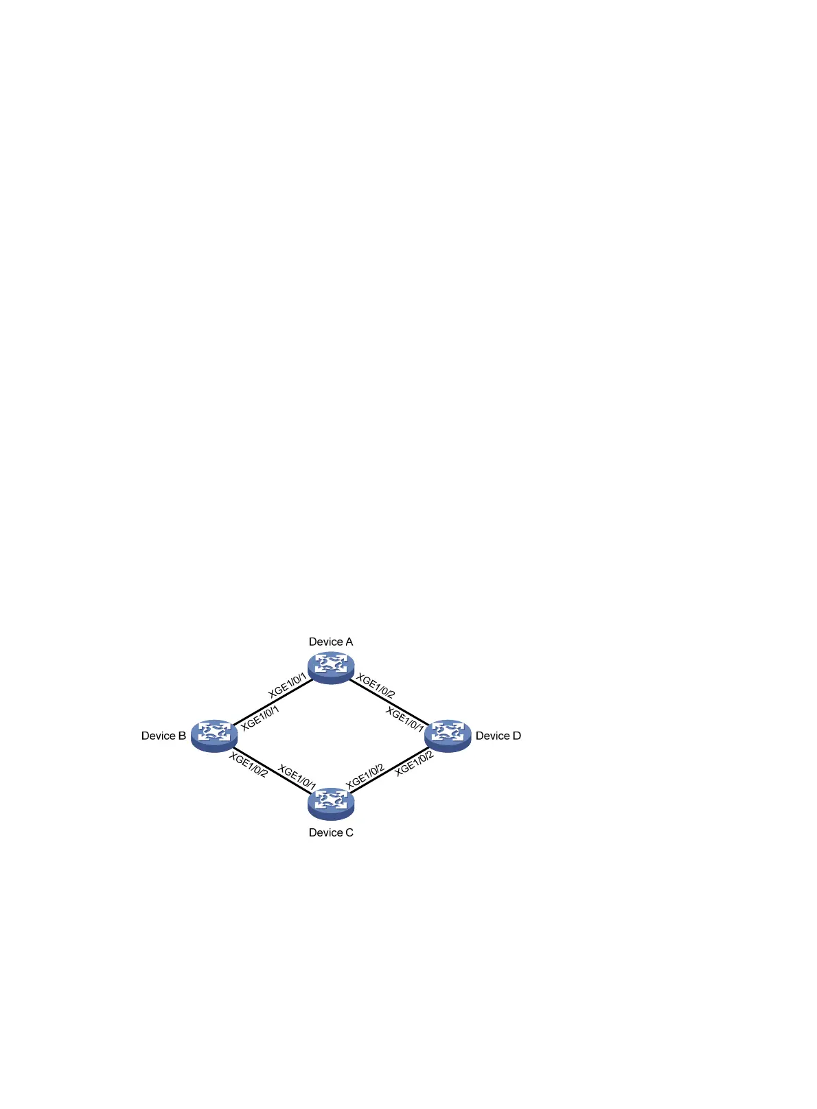
As shown in Figure 14:
• Device C is a Smart Link device. Device A, Device B, and Device D are associated devices. Traffic
of VLANs 1 through 200 on Device C is dually uplinked to Device A by Device B and Device D.
• Implement dual uplink backup and load sharing on Device C: Traffic of VLANs 1 through 100 is
uplinked to Device A by Device B. Traffic of VLANs 101 through 200 is uplinked to Device A by
Device D.
Figure 14 Network diagram
Configuration procedure
1. Configure Device C:
# Create VLAN 1 through VLAN 200, map VLANs 1 through 100 to MSTI 1, and VLANs 101
through 200 to MSTI 2, and activate MST region configuration.
<DeviceC> system-view
[DeviceC] vlan 1 to 200
[DeviceC] stp region-configuration

 Loading...


