89
Task Command
Display the states of IPv6 VRRP
groups.
display vrrp ipv6 [ interface interface-type interface-number [ vrid
virtual-router-id ] ] [ verbose ]
Display statistics for IPv6 VRRP
groups.
display vrrp ipv6 statistics [ interface interface-type interface-number
[ vrid virtual-router-id ] ]
Clear statistics for IPv6 VRRP
groups.
reset vrrp ipv6 statistics [ interface interface-type interface-number [ vrid
virtual-router-id ] ]
IPv4 VRRP configuration examples
This section provides examples of configuring IPv4 VRRP applications on switches.
Single VRRP group configuration example
This section provides an example of configuring a single VRRP group on switches.
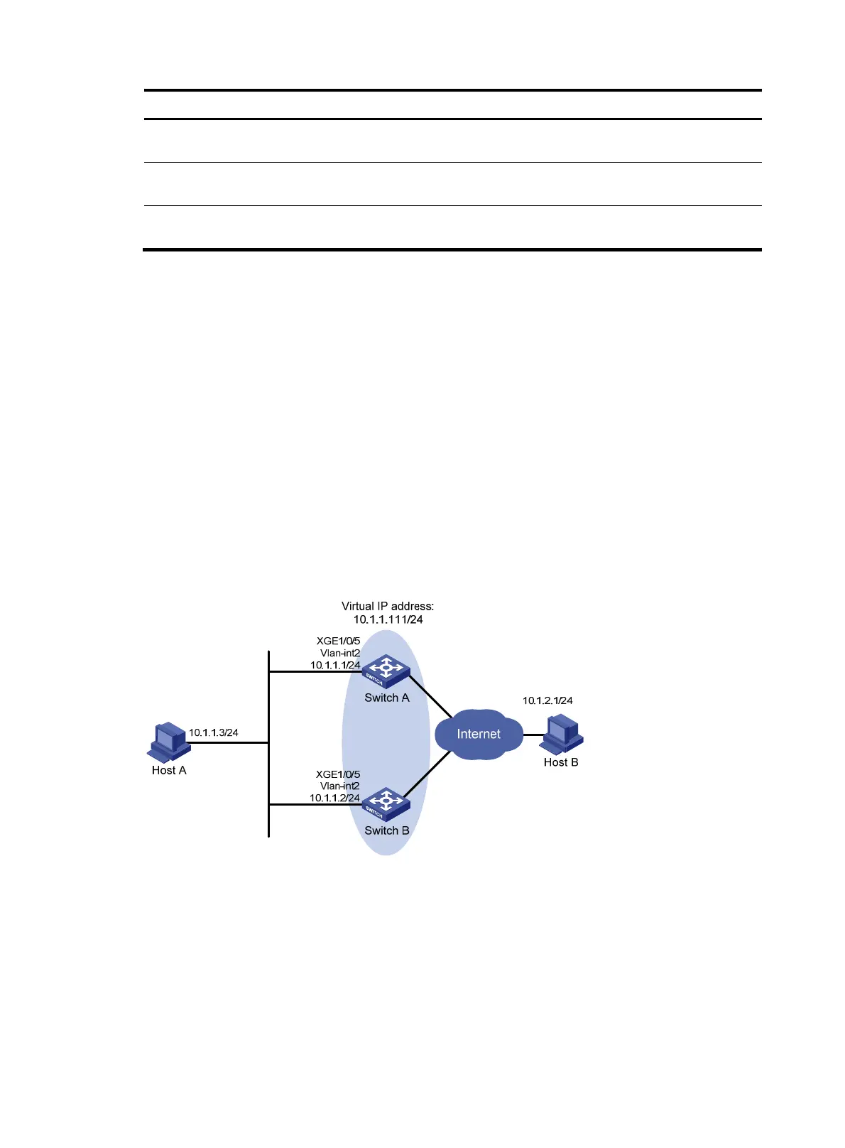
Network requirements
Switch A and Switch B form a VRRP group and use the virtual IP address 10.1.1.111/24 to provide gateway
service for the subnet where Host A resides, as shown in Figure 26.
Sw
itch A operates as the master to forward packets from Host A to Host B. When Switch A fails, Switch
B takes over to forward packets for Host A.
Figure 26 Network diagram
Configuration procedure
1. Configure Switch A:
# Configure VLAN 2.
<SwitchA> system-view
[SwitchA] vlan 2
[SwitchA-vlan2] port ten-gigabitethernet 1/0/5
[SwitchA-vlan2] quit
[SwitchA] interface vlan-interface 2

 Loading...


