92
Multiple VRRP groups configuration example
This section provides an example of configuring multiple VRRP groups on switches.
Network requirements
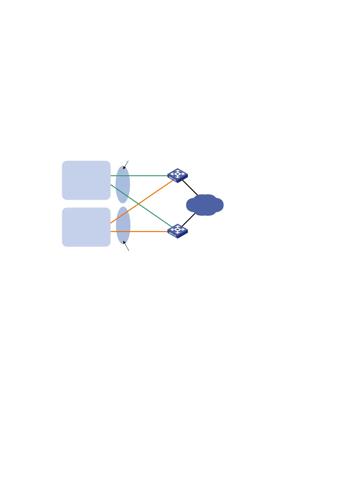
Switch A and Switch B form two VRRP groups. VRRP group 1 uses the virtual IP address 10.1.1.100/25 to
provide gateway service for hosts in VLAN 2, and VRRP group 2 uses the virtual IP address
10.1.1.200/25 to provide gateway service for hosts in VLAN 3, as shown in Figure 27.
As
si
gn a higher priority to Switch A than Switch B in VRRP group 1, but a lower priority in VRRP group
2, to distribute the traffic from VLAN 2 and VLAN 3 between the two switches. When one of the switches
fails, the healthy switch provides gateway service for both VLANs.
Figure 27 Network diagram
Configuration procedure
1. Configure Switch A:
# Configure VLAN 2.
<SwitchA> system-view
[SwitchA] vlan 2
[SwitchA-vlan2] port ten-gigabitethernet 1/0/5
[SwitchA-vlan2] quit
[SwitchA] interface vlan-interface 2
[SwitchA-Vlan-interface2] ip address 10.1.1.1 255.255.255.128
# Create VRRP group 1, and set its virtual IP address to 10.1.1.100.
[SwitchA-Vlan-interface2] vrrp vrid 1 virtual-ip 10.1.1.100
# Assign Switch A a higher priority than Switch B in VRRP group 1, so Switch A can become the
master in the group.
[SwitchA-Vlan-interface2] vrrp vrid 1 priority 110
[SwitchA-Vlan-interface2] quit
# Configure VLAN 3.
[SwitchA] vlan 3
[SwitchA-vlan3] port ten-gigabitethernet 1/0/6
[SwitchA-vlan3] quit
Switch A
Switch B
Virtual IP address 1:
10.1.1.100/25
Virtual IP address 2:
10.1.1.200/25
XGE1/0/5
Vlan-int2
10.1.1.1/25
XGE1/0/5
Vlan-int2
10.1.1.2/25
Internet
VLAN 2
Gateway:
10.1.1.100/25
VLAN 3
Gateway:
10.1.1.200/25
XGE1/0/6
Vlan-int3
10.1.1.130/25
XGE1/0/6
Vlan-int3
10.1.1.131/25

 Loading...


