109
VRRP load balancing configuration example
This section provides an example of configuring the VRRP load balancing mode.
Network requirements
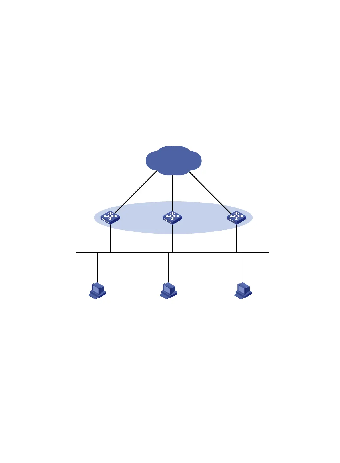
Switch A, Switch B, and Switch C form a load balanced VRRP group and use the virtual IPv6 addresses
FE80::10 and 1::10 to provide gateway service for subnet 1::/64, as shown in Figure 31.
Hosts on subnet 1
::/64 learn 1::10 as their default gateway from RA messages sent by the switches.
Configure VFs on Switch A, Switch B, or Switch C to monitor their respective VLAN-interface 3. When the
interface on any of them fails, the weights of the VFs on the problematic switch decrease so another AVF
can take over.
Figure 31 Network diagram
Configuration procedure
1. Configure Switch A:
# Configure VLAN 2.
<SwitchA> system-view
[SwitchA] vlan 2
[SwitchA-vlan2] port ten-gigabitethernet 1/0/5
[SwitchA-vlan2] quit
# Configure VRRP to operate in load balancing mode.
[SwitchA] vrrp ipv6 mode load-balance
# Create VRRP group 1, and set its virtual IPv6 addresses to FE80::10 and 1::10.
[SwitchA] interface vlan-interface 2
[SwitchA-Vlan-interface2] ipv6 address fe80::1 link-local
IP: 1::4/64
Gateway IP: 1::10
Host A Host B Host C
Switch A Switch B Switch C
XGE1/0/5
Vlan-int2
IP: FE80::1; 1::1/64
VIP: FE80::10; 1::10
Network
XGE1/0/5
Vlan-int2
IP: FE80::2; 1::2/64
VIP: FE80::10; 1::10
XGE1/0/5
Vlan-int2
IP: FE80::3; 1::3/64
VIP: FE80::10; 1::10
Master
AVF 1
Backup
AVF 2
Backup
AVF 3
IP: 1::5/64
Gateway IP: 1::10
IP: 1::6/64
Gateway IP: 1::10
Vlan-int3
Vlan-int3
Vlan-int3

 Loading...


