148
# Verify that the hosts in subnet 30.1.1.0/24 can communicate with the hosts in subnet 20.1.1.0/24 when
the master route fails.
[SwitchB] ping -a 30.1.1.1 20.1.1.1
Ping 20.1.1.1: 56 data bytes, press CTRL_C to break
Reply from 20.1.1.1: bytes=56 Sequence=1 ttl=254 time=2 ms
Reply from 20.1.1.1: bytes=56 Sequence=2 ttl=254 time=1 ms
Reply from 20.1.1.1: bytes=56 Sequence=3 ttl=254 time=1 ms
Reply from 20.1.1.1: bytes=56 Sequence=4 ttl=254 time=1 ms
Reply from 20.1.1.1: bytes=56 Sequence=5 ttl=254 time=1 ms
--- Ping statistics for 20.1.1.1 ---
5 packet(s) transmitted, 5 packet(s) received, 0.00% packet loss
round-trip min/avg/max/std-dev = 1/1/2/1 ms
Static routing-Track-BFD collaboration configuration example
Network requirements
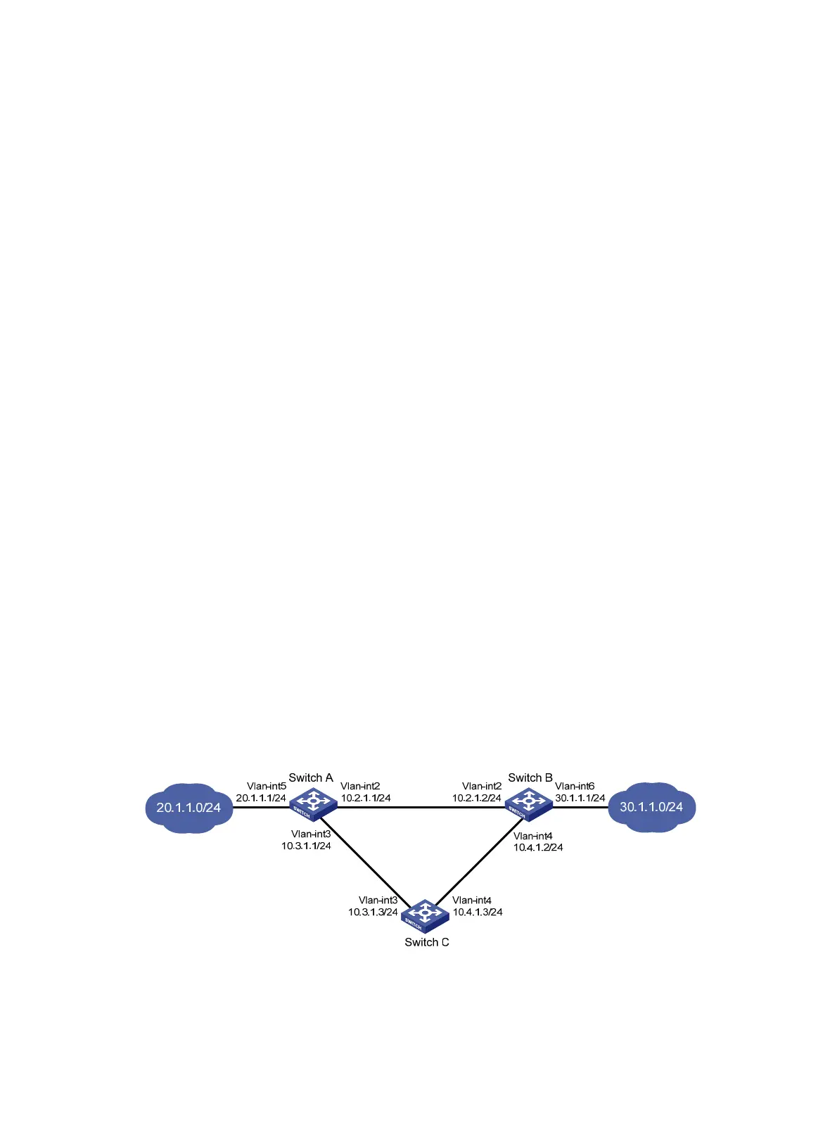
As shown in Figure 37:
• Switch A is the default gateway of the hosts in subnet 20.1.1.0/24.
• Switch B is the default gateway of the hosts in subnet 30.1.1.0/24.
• Hosts in the two subnets communicate with each other through static routes.
To ensure network availability, configure route backup and static routing-Track-BFD collaboration on
Switch A and Switch B as follows:
• On Switch A, assign a higher priority to the static route to 30.1.1.0/24 with Switch B as the next hop.
This route is the master route. The static route to 30.1.1.0/24 with Switch C as the next hop acts as
the backup route. When the master route is unavailable, BFD can quickly detect the route failure to
make the backup route take effect.
• On Switch B, assign a higher priority to the static route to 20.1.1.0/24 with Switch A as the next hop.
This route is the master route. The static route to 20.1.1.0/24 with Switch C as the next hop acts as
the backup route. When the master route is unavailable, BFD can quickly detect the route failure to
make the backup route take effect.
Figure 37 Network diagram
Configuration procedure
1. Create VLANs and assign ports to them. Configure the IP address of each VLAN interface as
shown in Figure 37. (Details not shown.)

 Loading...


