106
Assign Switch A a higher priority than Switch B in VRRP group 1 but a lower priority in VRRP group 2 to
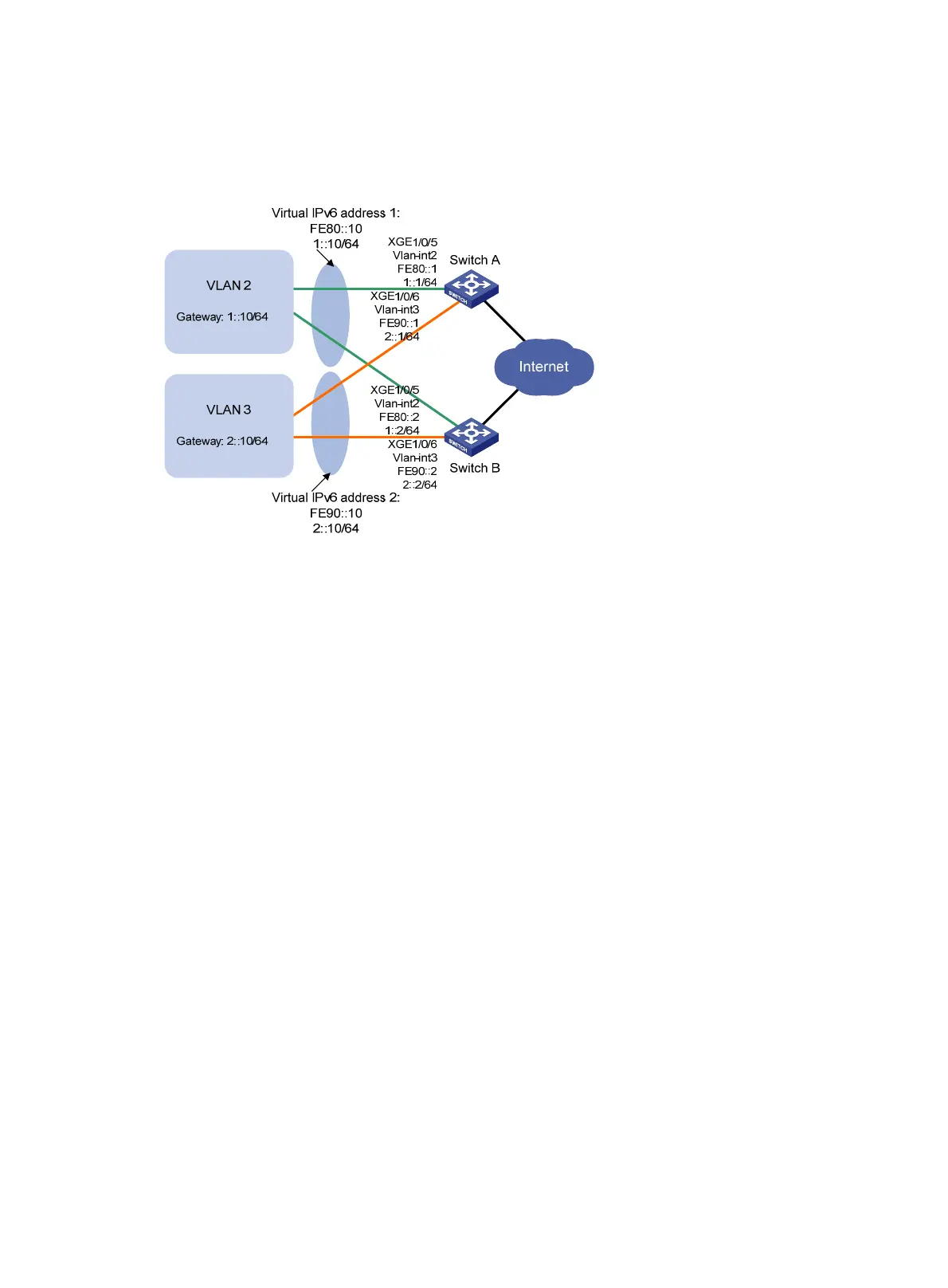
distribute the traffic from VLAN 2 and VLAN 3 between the two switches. When one of the switches fails,
the healthy switch provides gateway service for both VLANs.
Figure 30 Network diagram
Configuration procedure
1. Configure Switch A:
# Configure VLAN 2.
<SwitchA> system-view
[SwitchA] vlan 2
[SwitchA-vlan2] port ten-gigabitethernet 1/0/5
[SwitchA-vlan2] quit
[SwitchA] interface vlan-interface 2
[SwitchA-Vlan-interface2] ipv6 address fe80::1 link-local
[SwitchA-Vlan-interface2] ipv6 address 1::1 64
# Create VRRP group 1, and set its virtual IPv6 addresses to FE80::10 to 1::10.
[SwitchA-Vlan-interface2] vrrp ipv6 vrid 1 virtual-ip fe80::10 link-local
[SwitchA-Vlan-interface2] vrrp ipv6 vrid 1 virtual-ip 1::10
# Assign Switch A a higher priority than Switch B in VRRP group 1, so Switch A can become the
master in the group.
[SwitchA-Vlan-interface2] vrrp ipv6 vrid 1 priority 110
# Enable Switch A to send RA messages, so hosts in VLAN 2 can learn the default gateway
address.
[SwitchA-Vlan-interface2] undo ipv6 nd ra halt
[SwitchA-Vlan-interface2] quit
# Configure VLAN 3.
[SwitchA] vlan 3
[SwitchA-vlan3] port ten-gigabitethernet 1/0/6
[SwitchA-vlan3] quit
[SwitchA] interface vlan-interface 3
[SwitchA-Vlan-interface3] ipv6 address fe90::1 link-local

 Loading...


