I
-
System Measurements
Making System Measurements
16:31:83
DEC
86,
1993
@
REF 37.5
dBmV hT
10
dB
ml!
ST0
AIR
m
HRCT
USR CH 0
CNTR FRO
USR CH 9
SPAN
CENTER 57.888
NHz
RES
SW
38
kHz
Pf-RV
MQflU
SPAN
6.888
MHz
UBW
38
kHz
SWP
20.0
msec
RT
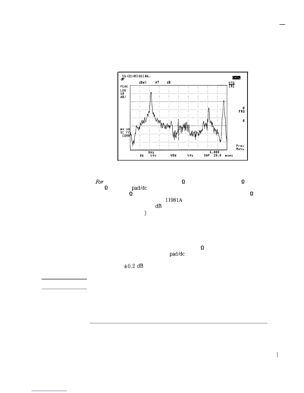
Figure 3-1. Channel Tuning Menu
4. Fbr
spectrum
analyzers with a 50
D
input:
Use an external 50
61
to
75
61
matching pad/de block to compensate for the impedance mismatch
between a 75
62
impedance system and the spectrum analyzer’s 50
hl
input
impedance. If you use an HP
11981A
external pad, the external pad
causes approximately 5.8
dB
of amplitude loss. The external pad function
(EXT PAD YES NO
)
can be used to compensate for this amplitude loss.
l Connect the matching pad to the spectrum analyzer input.
l Press Analyzer Input EXT PAD YES NO to underline YES.
l Press Prev Menu to return to the Setup menu.
If you are using a spectrum analyzer with 50
Q
input impedance but are
not using an external matching pad/de block, the analyzer will compensate
for most of the impedance mismatch, but amplitude measurements can
have up to
4~0.2
dB
additional error caused by the uncompensated
mismatch over the frequency range.
CAUTION
dc voltages in excess of 25 V and ac power-line voltages in excess of
100 Vpeak can permanently damage the analyzer input.
3-5