Notice that the end node devices are connected to the switch by straight-through or crossover
twisted-pair cables. Either cable type can be used because of the “IEEE Auto MDI/MDI-X” features
on the switch.
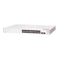
Figure 31 Example as a Desktop Switch Implementing PoE/PoE+
This illustration is an example of the switch being configured to supply PoE/PoE+ power to end
devices such as IP telephones and wireless access points (WAPs).
As shown in Example as a Desktop Switch Implementing PoE/PoE+, the IP telephones can be
connected in line, that is, between the switch and the end device, in this case a PC. The IP
telephones in this illustration have two ports, one in and one out. Therefore the phone receives
voice and power from the switch, and the PC can send and receive data through the phone to
the switch.
The end node devices are connected to the switch by straight-through or crossover twisted-pair
cables. Either cable type can be used because of the “IEEE Auto MDI/MDI-X” features on the
switch.
54 Installing the Switch

 Loading...