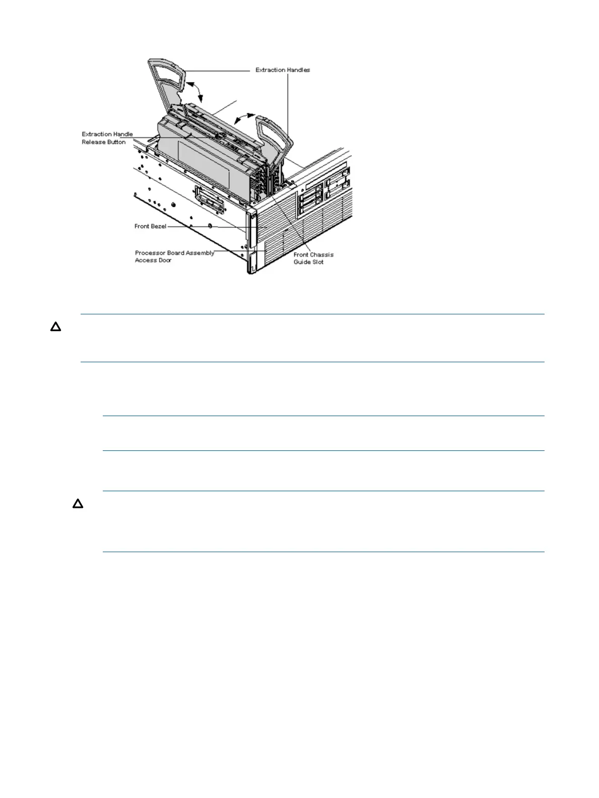
Figure 7 Removing and Replacing the Memory Carrier Assembly
Replacing the Memory Carrier Assembly
CAUTION: Ensure that the processor board assembly is fully seated before you replace the
memory carrier assembly. The processor board assembly access door must be flush with the front
bezel.
To replace the memory carrier assembly, follow these steps:
1. Ensure the extraction handles are positioned in the outward, unlocked position.
2. Align the memory carrier assembly with the front and rear chassis guide slots.
NOTE: Assembly side 0 is on the left, and assembly side 1 is on the right as viewed from
the front of the chassis.
3. Slide the memory carrier assembly into the chassis until it begins to seat into the socket located
on the processor board.
CAUTION: Do not apply excessive force when closing the extraction handles and seating
the memory carrier assembly into the socket on the processor board. Manipulate the extraction
handles with care. Failure to observe these cautions can result in damage to the extraction
handles and other server components.
4. Rotate the extraction handles inward and press the handles straight down until they snap into
the locked position.
5. Replace the memory carrier assembly cover and latch the top cover release lever closed. See
“Replacing the Memory Carrier Assembly Cover” (page 13).
22 Installing the System
 Loading...


