Installing System Memory DIMMs
System memory or DIMMs are located on a pair of memory boards inside the memory carrier
assembly.
WARNING! Ensure that the system is powered off and all power sources have been disconnected
from the server prior to performing this procedure.
Voltages are present at various locations within the server whenever an AC power source is
connected. This voltage is present even when the main power switch is in the off position.
Failure to observe this warning can result in personal injury or damage to equipment.
CAUTION: Observe all ESD safety precautions before attempting this procedure. Failure to follow
ESD safety precautions can result in damage to the server.
Figure 7 (page 22) shows the memory carrier assembly removed from the chassis.
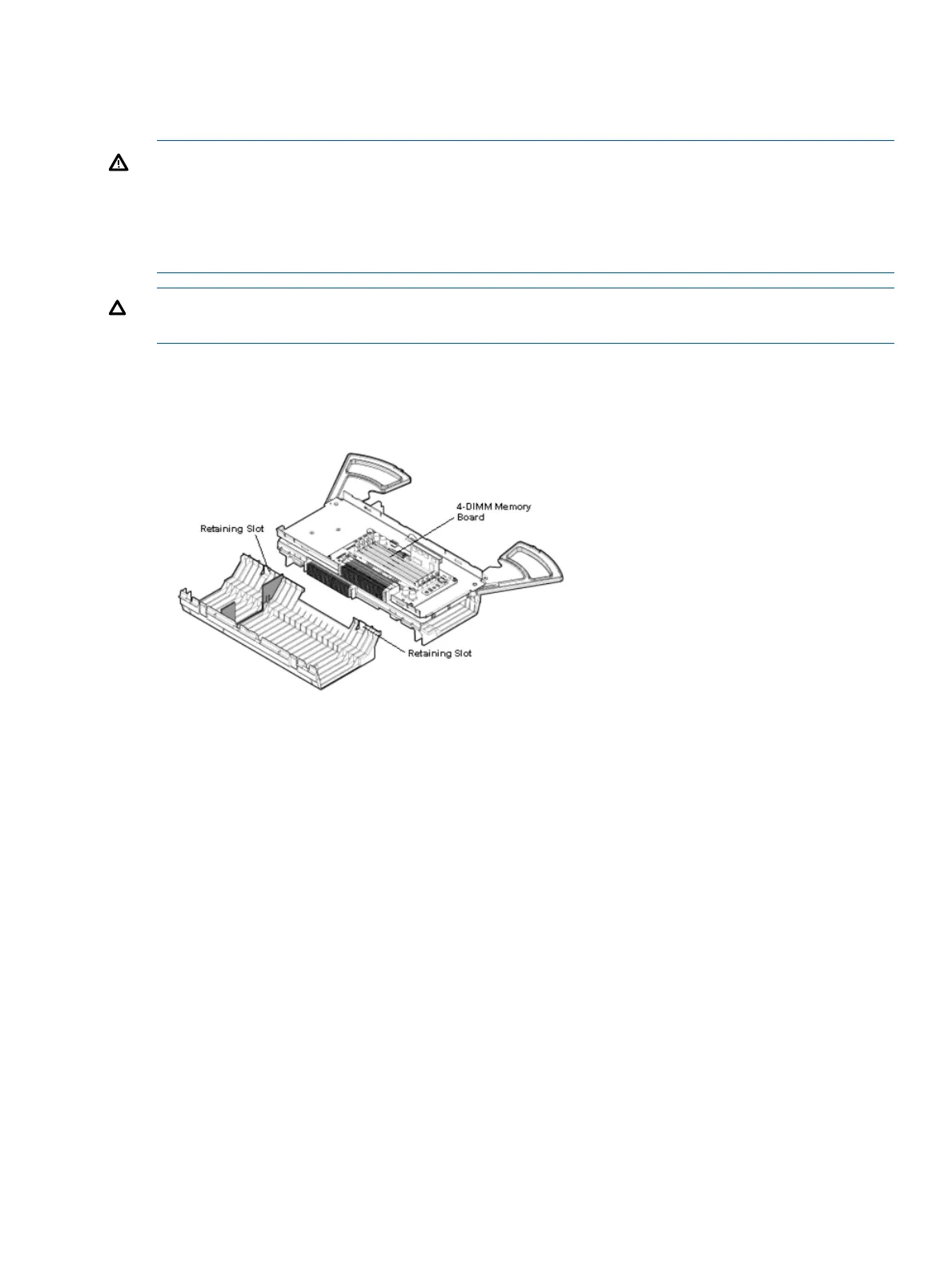
Figure 8 shows the memory carrier with the side cover removed.
Figure 8 Memory Carrier Assembly with Side Cover Removed
Memory Installation Conventions
Before installing memory, read and understand the following memory installation conventions:
• Supported DIMM sizes and memory configurations
• DIMM load order
• DIMM slot IDs
Supported DIMM Sizes and Memory Configurations
The standard server configuration includes an 8-DIMM memory carrier which contains two 4-DIMM
memory boards. An optional, high-capacity memory configuration is also available: a 24-DIMM
memory carrier containing two 12-DIMM memory boards.
System DIMMs seat onto the memory boards. The minimum server configuration requires at least
one memory pair in the 8-DIMM memory carrier, and one memory quad (group of four DIMMs)
in the 24-DIMM memory carrier.
The following are the supported DIMM sizes for the server:
• 512 MB
• 1 GB
• 2 GB
Installing Additional Components 23
 Loading...


