17. Replace the memory carrier assembly cover and latch the top cover release lever closed. See
“Replacing the Memory Carrier Assembly Cover” (page 13).
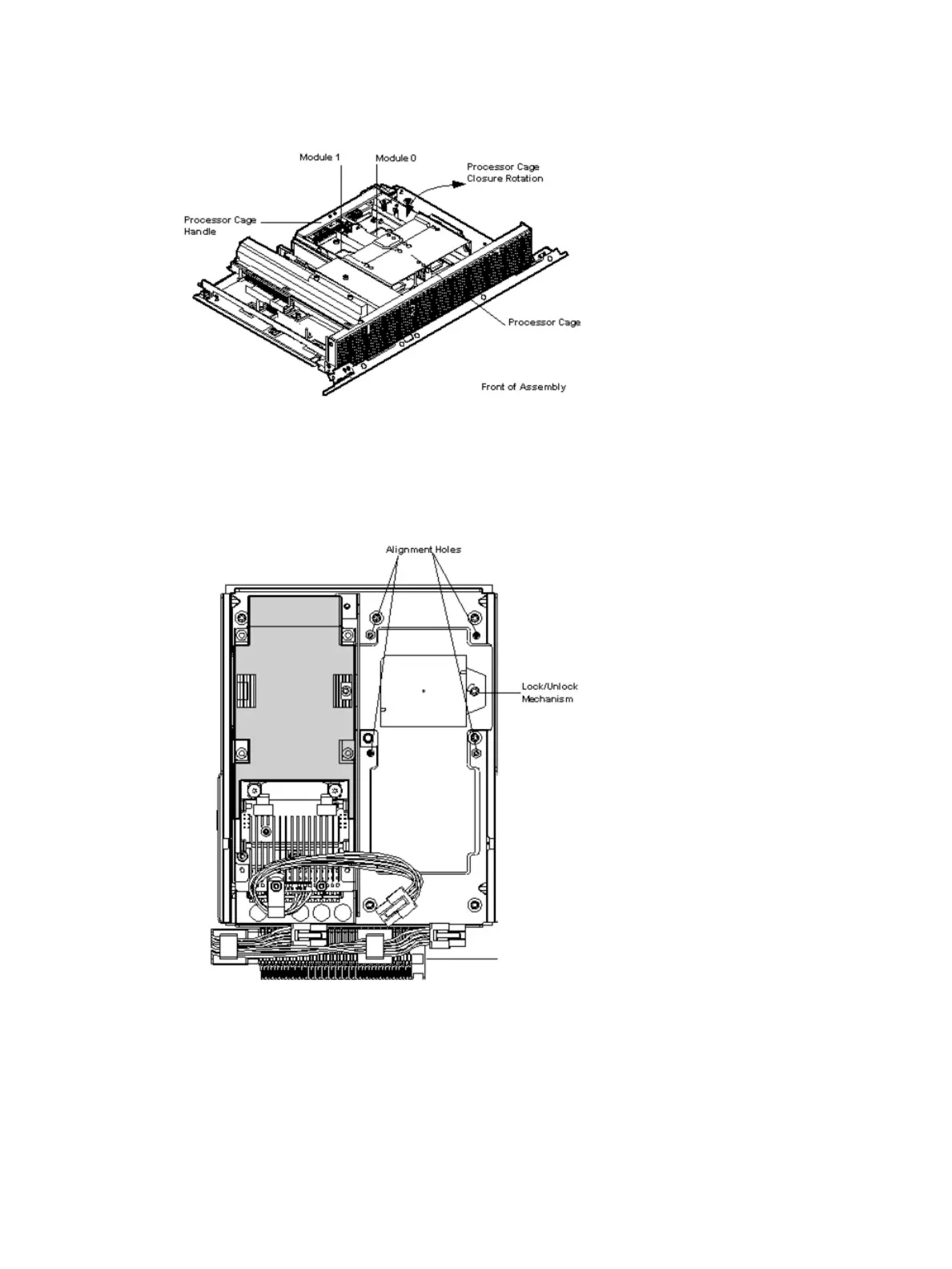
Figure 13 Processor Board Assembly (Front View)
Figure 14 shows the power connectors, the processor lock / unlock mechanism location and the
alignment holes. One processor is installed in the illustration.
Figure 14 Processor Alignment Holes and Lock/Unlock Mechanism
Installing the Server into a Rack or Pedestal Mount
This section provides instructions on how to install the server into a rack or a pedestal mount.
Installing the Server into a Rack
The following information describes how to install the server into an HP rack or an approved non-HP
rack.
32 Installing the System
 Loading...


