Removal and replacement procedures 51
3.
Remove the primary access panel ("Primary access panel" on page 29).
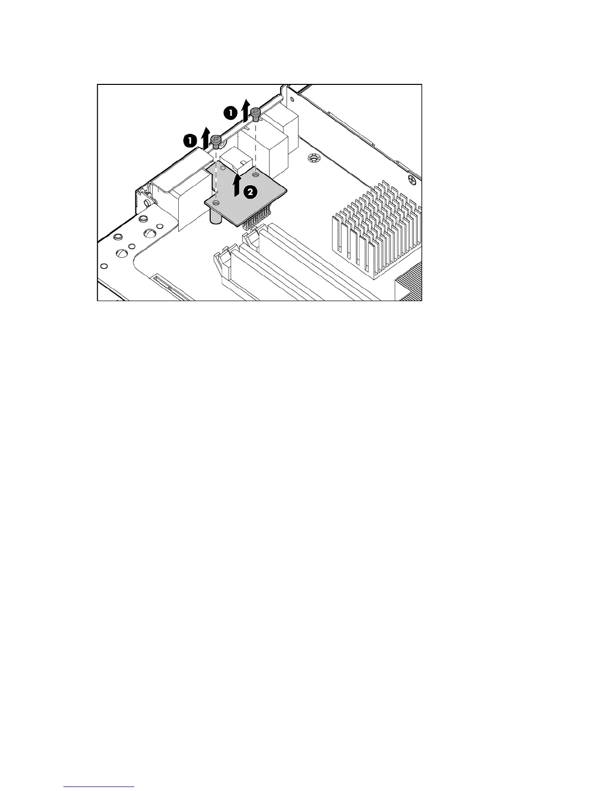
4. Remove the iLO connector module.
To replace the component, reverse the removal procedure.
System board
To remove the component:
1. Power down the server (on page 27).
2. Remove the server from the rack (on page 28).
3. Remove the primary access panel ("Primary access panel" on page 29).
4. Remove the secondary access panel (on page 28).
5. Remove the PCI riser board assembly ("PCI riser board assembly" on page 41).
6. Remove all DIMMs ("DIMMs" on page 31).
7. Remove the air baffle ("Processor air baffle" on page 32).
8. Remove the fan assembly ("Fan assembly" on page 32).
9. Disconnect the power supply cables from the system board ("Server cabling" on page 75).
10. Disconnect the SATA hard drive cables from the system board ("Cabling" on page 75).
11. Disconnect the hard drive cage cables and the front panel/LED cable from the system board
("Cabling overview" on page 75).
12. Remove the dedicated iLO connector module, if installed ("Dedicated iLO connector module" on
page 50).
13. Remove the heatsink ("Heatsink" on page 44).
 Loading...