Figures
11
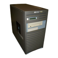
Figure 1-1. Front Panel Components . . . . . . . . . . . . . . . . . . . . . . . . . . . . . . . . . . . . . . . . . . 18
Figure 1-2. LCD Symbols . . . . . . . . . . . . . . . . . . . . . . . . . . . . . . . . . . . . . . . . . . . . . . . . . . . 18
Figure 1-3. CD Drive Features . . . . . . . . . . . . . . . . . . . . . . . . . . . . . . . . . . . . . . . . . . . . . . 19
Figure 1-4. Floppy Disk Drive Features. . . . . . . . . . . . . . . . . . . . . . . . . . . . . . . . . . . . . . . . 21
Figure 1-5. Rear Panel Components. . . . . . . . . . . . . . . . . . . . . . . . . . . . . . . . . . . . . . . . . . . 22
Figure 1-6. Audio Connectors . . . . . . . . . . . . . . . . . . . . . . . . . . . . . . . . . . . . . . . . . . . . . . . . 25
Figure 1-7. Security Loop Components . . . . . . . . . . . . . . . . . . . . . . . . . . . . . . . . . . . . . . . . 26
Figure 1-8. Closed Left Side Panel . . . . . . . . . . . . . . . . . . . . . . . . . . . . . . . . . . . . . . . . . . . . 26
Figure 2-1. CD Drive Jumper Setting (Rear View) . . . . . . . . . . . . . . . . . . . . . . . . . . . . . . . 37
Figure 2-2. Memory Slot Numbers and Loading Sequence . . . . . . . . . . . . . . . . . . . . . . . . 38
Figure 2-3. PCI Card Slot Numbering and Capabilities. . . . . . . . . . . . . . . . . . . . . . . . . . . 39
Figure 3-1. Main (Power on LCD) Troubleshooting Flowchart. . . . . . . . . . . . . . . . . . . . . . 43
Figure 3-2. Console Troubleshooting Flowchart . . . . . . . . . . . . . . . . . . . . . . . . . . . . . . . . . 44
Figure 3-3. Bootable Device Troubleshooting Flowchart . . . . . . . . . . . . . . . . . . . . . . . . . . 45
Figure 3-4. HP-UX Troubleshooting Flowchart . . . . . . . . . . . . . . . . . . . . . . . . . . . . . . . . . 46
Figure 3-5. Fan Locations . . . . . . . . . . . . . . . . . . . . . . . . . . . . . . . . . . . . . . . . . . . . . . . . . . . 49
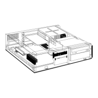
Figure 4-1. Exploded View Diagram of the B2000 Workstation FRUs . . . . . . . . . . . . . . . 83
Figure 4-2. Opening the Front Panel . . . . . . . . . . . . . . . . . . . . . . . . . . . . . . . . . . . . . . . . . . 87
Figure 4-3. Opening the Left Side Panel . . . . . . . . . . . . . . . . . . . . . . . . . . . . . . . . . . . . . . . 88
Figure 4-4. Removing the Power Switch/LCD Assembly . . . . . . . . . . . . . . . . . . . . . . . . . . 90
Figure 4-5. Removing the CD Drive Bay’s Rear Cover . . . . . . . . . . . . . . . . . . . . . . . . . . . . 91
Figure 4-6. Front of the Workstation with the Front Panel Removed . . . . . . . . . . . . . . . . 92
Figure 4-7. Removing the CD Drive. . . . . . . . . . . . . . . . . . . . . . . . . . . . . . . . . . . . . . . . . . . 92
Figure 4-8. Installing the CD Drive . . . . . . . . . . . . . . . . . . . . . . . . . . . . . . . . . . . . . . . . . . . 93
Figure 4-9. Tightening the Bracket Screws . . . . . . . . . . . . . . . . . . . . . . . . . . . . . . . . . . . . . 94
Figure 4-10. Plugging in the Audio, ATAPI, and Power Cables . . . . . . . . . . . . . . . . . . . . . 94
Figure 4-11. Replacing the CD Drive Bay’s Rear Cover . . . . . . . . . . . . . . . . . . . . . . . . . . . 95
Figure 4-12. Removing the Floppy Disk Drive Bay’s Rear Cover. . . . . . . . . . . . . . . . . . . . 96
Figure 4-13. Front of Workstation with the Front Panel Removed . . . . . . . . . . . . . . . . . . 97
Figure 4-14. Removing the Floppy Disk Drive . . . . . . . . . . . . . . . . . . . . . . . . . . . . . . . . . . 97
Figure 4-15. Installing the Floppy Disk Drive Blank and Bracket . . . . . . . . . . . . . . . . . . 98
Figure 4-16. Tightening the Bracket Screws . . . . . . . . . . . . . . . . . . . . . . . . . . . . . . . . . . . . 98
Figure 4-17. Replacing the Floppy Disk Drive Bay’s Rear Cover. . . . . . . . . . . . . . . . . . . . 99
Figure 4-18. Removing the Floppy Disk Drive Bay’s Rear Cover. . . . . . . . . . . . . . . . . . . 100
Figure 4-19. Front of Workstation with the Front Panel Removed . . . . . . . . . . . . . . . . . 100
Figure 4-20. Removing the Floppy Disk Drive Bracket and Blank . . . . . . . . . . . . . . . . . 101
Figure 4-21. Installing the Floppy Disk Drive. . . . . . . . . . . . . . . . . . . . . . . . . . . . . . . . . . 102
Figure 4-22. Tightening the Bracket Screws . . . . . . . . . . . . . . . . . . . . . . . . . . . . . . . . . . . 102
Figure 4-23. Plugging in the Power and Data Cables . . . . . . . . . . . . . . . . . . . . . . . . . . . . 103