Do you have a question about the HP Vectra and is the answer not in the manual?
Overview of the HP Vectra PC's system architecture, expansion capabilities, and compatibility.
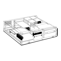
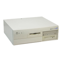
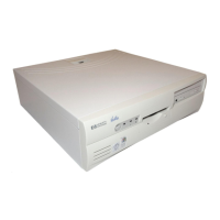
Describes the basic components found in typical HP Vectra PC systems, including the system processing unit.
Defines the HP Vectra PC system specifications and operating environment parameters.
Details system RAM, ROM, refresh cycles, parity, and memory map configurations for the processor board.
Explains the Intel 80286 microprocessor, its real-address and protected modes of operation.
Describes the generation of the 80286 processor clock signal and its synchronization features.
Discusses the HP Vectra PC's performance, including clock speeds and wait-state generation for data transfers.
Details the Intel 8254 timer/counter device and its three independent 16-bit counters for system functions.
Explains the 80286 microprocessor's non-maskable interrupt and the 19-level interrupt controller system.
Describes the DMA control provided by Intel 8237A chips, including clock cycles, channels, and address generation.
Covers the backplane I/O channel support for accessory cards, including interrupt levels and DMA channels.
Describes the HP Vectra PC's internal speaker and how it is driven by I/O port output or timer.
Defines the pin assignments for the Power/Battery connector (P3) on the system.
Details the MC146818 RT/CMOS chip for accurate real-time clock and CMOS RAM functions with battery backup.
Explains the three jumpers on the processor board used to configure the flexible disc controller subsystem.
Summarizes BIOS interrupt vectors, their range, entry points, and functions for system operations.
Describes the 8041 microcomputer functioning as the keyboard controller, managing communication paths.
Explains the HP-Human Interface Link for connecting keyboards and input devices via a 4-pin connector.
Details how keyboard scan codes are reported to the HP-HIL controller and processed by the 80286.
Describes how BIOS commands are sent to the keyboard, programming LEDs and handling interrupts.
Discusses the user-selectable line voltage levels and fuse protection for the power supply.
Specifies the AC inrush current limitation for the power supply under all conditions.
Explains the power supply's ability to maintain regulated operation during brief input voltage drops.
Details the five output power supply voltages provided by the HP Vectra PC.
Describes the switched AC outlet on the power supply, its wattage, and inrush current capacity.
Explains that outputs can open without damage and do not exceed overvoltage specifications.
Details the overvoltage protection mechanism and the reset procedure required after activation.
Describes the power supply fan's role in cooling system components with a specified CFM rating.
Outlines the average power support per I/O channel and the total power not to be exceeded for backplane slots.
Explains the PFAIL signal indicating power supply validity and its role in triggering power-down mode and system reset.
Details the operating clock frequencies of the HP45981A from the master oscillator and backplane.
Explains the HP45981A's interface to the 80286 as an 8-bit memory and I/O device with buffered signals.
Describes the 128 Kbyte character generator ROM containing four character sets for the HP45981A.
Covers the 32K RAM on the HP45981A, its asynchronous operation, wait-states, and access methods.
Details the operating modes of the video adapter card, including alphanumeric and graphics modes with resolutions.
Discusses the 6845 CRT controller chip, its internal registers, and initial chip values.
Explains the translation circuit allowing 15kHz monitor applications to run on 25kHz monitors without modification.
Lists the I/O registers accessible to the programmer for controlling the video adapter's functions.
Describes the system's real-address mode at power-up and the 80287's compatibility with the 8087 coprocessor.
Explains how to place the coprocessor into protected mode for memory management and multitasking support.
Details the 80287's operation on the 16MHz clock and its communication with the 80286 via I/O ports.
Discusses how the 80287 coprocessor extends data types, registers, and instructions for the microprocessor.
Details the HP45811A drive, its specifications, and performance when installed in the HP Vectra PC.
Explains the interface between the 360KB flexible disc drive and the controller via control and DC power interfaces.
Describes the HP45812A drive, its purchase as an accessory, and its differences from the 360KB drive.
Provides performance specifications for the 1.2MB Internal Flexible Disc Drive when installed in the HP Vectra.
Covers the HP45816A and HP45817A hard disc subsystem cards and their intelligent controller implementation.
Explains memory parity checking, non-maskable interrupts for errors, and dynamic memory refresh.
Details the memory expansion card's clock cycles and the number of wait-states for memory access.
Describes how address selection switches (SW1, SW2) configure memory expansion cards for system address space.
Details the serial portion of the HP24540A card, its asynchronous communications, and features.
Describes the parallel port on the card for attaching devices and its programmable printer control features.
Overview of the HP Vectra PC's system architecture, expansion capabilities, and compatibility.
Describes the basic components found in typical HP Vectra PC systems, including the system processing unit.
Defines the HP Vectra PC system specifications and operating environment parameters.
Details system RAM, ROM, refresh cycles, parity, and memory map configurations for the processor board.
Explains the Intel 80286 microprocessor, its real-address and protected modes of operation.
Describes the generation of the 80286 processor clock signal and its synchronization features.
Discusses the HP Vectra PC's performance, including clock speeds and wait-state generation for data transfers.
Details the Intel 8254 timer/counter device and its three independent 16-bit counters for system functions.
Explains the 80286 microprocessor's non-maskable interrupt and the 19-level interrupt controller system.
Describes the DMA control provided by Intel 8237A chips, including clock cycles, channels, and address generation.
Covers the backplane I/O channel support for accessory cards, including interrupt levels and DMA channels.
Describes the HP Vectra PC's internal speaker and how it is driven by I/O port output or timer.
Defines the pin assignments for the Power/Battery connector (P3) on the system.
Details the MC146818 RT/CMOS chip for accurate real-time clock and CMOS RAM functions with battery backup.
Summarizes BIOS interrupt vectors, their range, entry points, and functions for system operations.
Describes the 8041 microcomputer functioning as the keyboard controller, managing communication paths.
Explains the HP-Human Interface Link for connecting keyboards and input devices via a 4-pin connector.
Details how keyboard scan codes are reported to the HP-HIL controller and processed by the 80286.
Describes how BIOS commands are sent to the keyboard, programming LEDs and handling interrupts.
Discusses the user-selectable line voltage levels and fuse protection for the power supply.
Specifies the AC inrush current limitation for the power supply under all conditions.
Explains the power supply's ability to maintain regulated operation during brief input voltage drops.
Details the five output power supply voltages provided by the HP Vectra PC.
Describes the switched AC outlet on the power supply, its wattage, and inrush current capacity.
Explains that outputs can open without damage and do not exceed overvoltage specifications.
Details the overvoltage protection mechanism and the reset procedure required after activation.
Describes the power supply fan's role in cooling system components with a specified CFM rating.
Outlines the average power support per I/O channel and the total power not to be exceeded for backplane slots.
Explains the PFAIL signal indicating power supply validity and its role in triggering power-down mode and system reset.
Details the operating clock frequencies of the HP45981A from the master oscillator and backplane.
Explains the HP45981A's interface to the 80286 as an 8-bit memory and I/O device with buffered signals.
Describes the 128 Kbyte character generator ROM containing four character sets for the HP45981A.
Covers the 32K RAM on the HP45981A, its asynchronous operation, wait-states, and access methods.
Details the operating modes of the video adapter card, including alphanumeric and graphics modes with resolutions.
Discusses the 6845 CRT controller chip, its internal registers, and initial chip values.
Explains the translation circuit allowing 15kHz monitor applications to run on 25kHz monitors without modification.
Lists the I/O registers accessible to the programmer for controlling the video adapter's functions.
Describes the system's real-address mode at power-up and the 80287's compatibility with the 8087 coprocessor.
Explains how to place the coprocessor into protected mode for memory management and multitasking support.
Details the 80287's operation on the 16MHz clock and its communication with the 80286 via I/O ports.
Discusses how the 80287 coprocessor extends data types, registers, and instructions for the microprocessor.
Details the HP45811A drive, its specifications, and performance when installed in the HP Vectra PC.
Explains the interface between the 360KB flexible disc drive and the controller via control and DC power interfaces.
Describes the HP45812A drive, its purchase as an accessory, and its differences from the 360KB drive.
Provides performance specifications for the 1.2MB Internal Flexible Disc Drive when installed in the HP Vectra.
Covers the HP45816A and HP45817A hard disc subsystem cards and their intelligent controller implementation.
Explains memory parity checking, non-maskable interrupts for errors, and dynamic memory refresh.
Details the memory expansion card's clock cycles and the number of wait-states for memory access.
Describes how address selection switches (SW1, SW2) configure memory expansion cards for system address space.
Details the serial portion of the HP24540A card, its asynchronous communications, and features.
Describes the parallel port on the card for attaching devices and its programmable printer control features.
| Processor | Intel Pentium |
|---|---|
| RAM | Up to 128 MB |
| Storage | HDD (capacity varies by model) |
| Operating System | Windows 95 |
| Graphics | Integrated |
| Ports | Serial, Parallel |
| Expansion Slots | ISA, PCI |