The address and interrupt
of
the
serial
port
is
defined in
the
following chart.
Primary Secondary
Address
3F8H
2F8H
Interrupt
4 3
Serial Port Interface
to
the
System
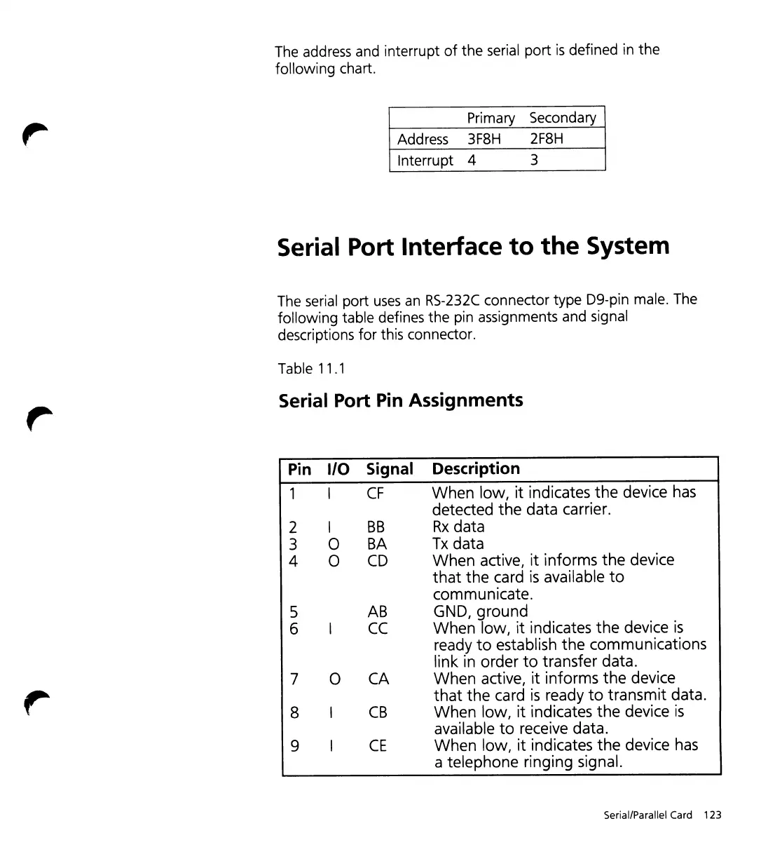
The serial port
uses
an
RS-232C
connector type D9-pin male. The
following table defines the pin assignments and signal
descriptions
for
this connector.
Table 11.1
Serial Port
Pin
Assignments
Pin I/O
Signal
Description
I
CF
When low, it indicates the device
has
detected the data carrier.
2 I
BB
Rx
data
3
0
BA
Tx
data
4
0
CD
When active, it informs the device
that the card
is
available
to
communicate.
S
AS
GND, ground
6
CC
When low, it indicates the device
is
ready
to
establish the communications
link
in
order
to
transfer data.
7
0
CA
When active, it informs the device
,.
that the card
is
ready
to
transmit data.
8
CS
When low, it indicates the device
is
available
to
receive data.
9
CE
When low, it indicates the device
has
a telephone ringing signal.
Serial/Parallel Card 123