37
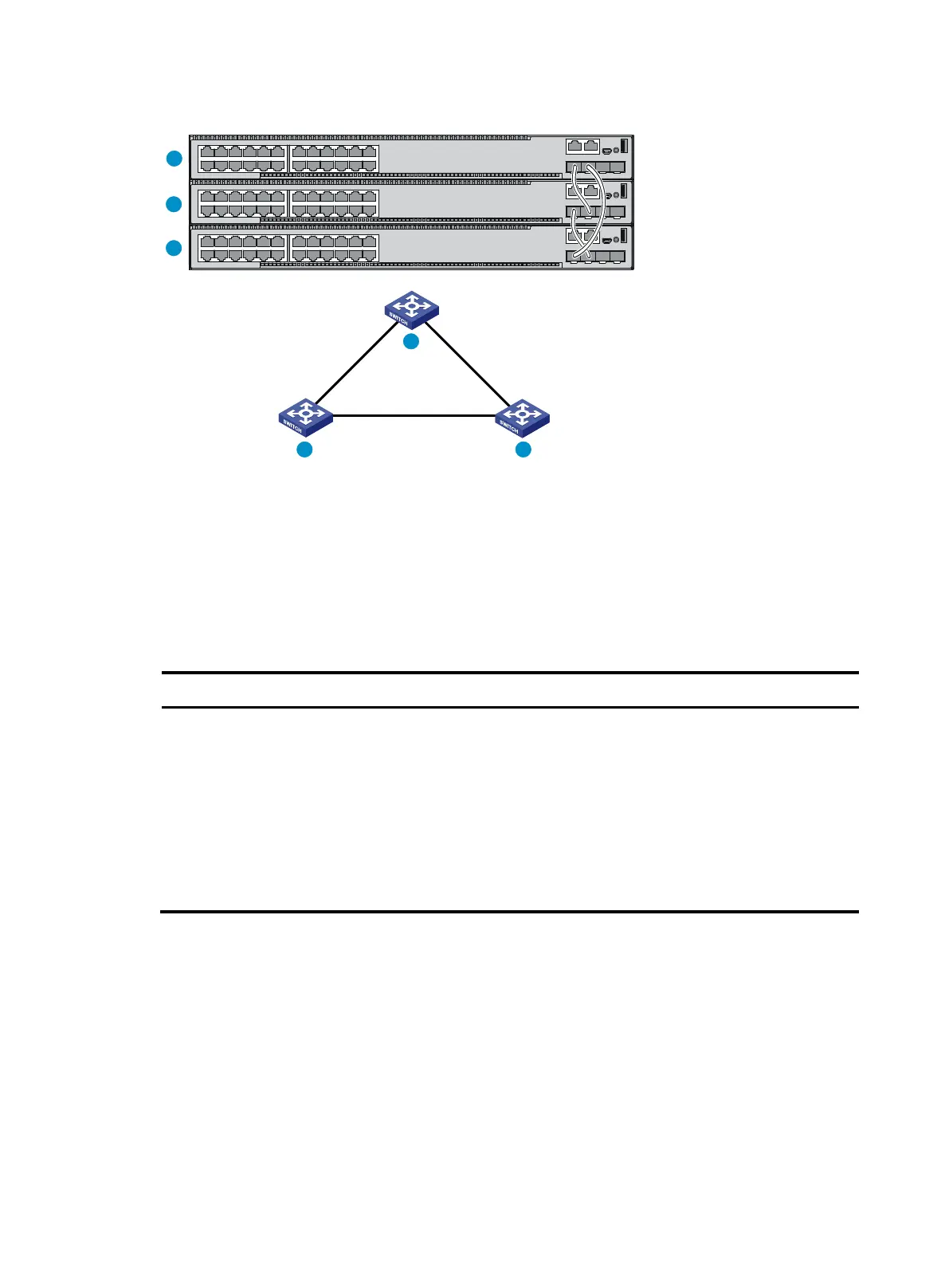
Figure 39 IRF fabric in ring topology
Identifying physical IRF ports on the member switches
Identify the physical IRF ports on the member switches according to your topology and connection
scheme.
Table 9 shows the physical ports that can be used for IRF connection and the port use restrictions.
Table 9 Physical IRF port requirements
Candidate physical IRF ports
Four fixed SFP+ ports on the front panel
Ports on the interface card on the rear panel
All physical ports to be bound to an IRF
port must be the same type.
If a QSFP+ port is split into four SFP+
ports, the QSFP+ port cannot be used
as a physical IRF port.
Planning the cabling scheme
Use SFP+/QSFP+ DAC cables or SFP+/QSFP+ transceiver modules and fibers to connect the IRF
member switches. If the IRF member switches are far away from one another, choose the SFP+/QSFP+
transceiver modules with optical fibers. If the IRF member switches are all in one equipment room, choose
SFP+/QSFP+ DAC cables. For more information about SFP+/QSFP+ DAC cables and SFP+/QSFP+
transceiver modules, see "Appendix C Ports and LEDs."
The following subsections describe several HPE recommended IRF connection schemes, and all these
schemes use a ring topology.
IRF-port1
IRF-port2
IRF-port1
IRF-port1
IRF-port2
IRF-port2
1
2
3
1
2 3

 Loading...


