Chapter 7 Detailed Function Introduction Shenzhen Hpmont Technology Co., Ltd.
- 42 - HD09-S Series User Manual V1.1
Ref. Code Function Description Setting Range [Default]
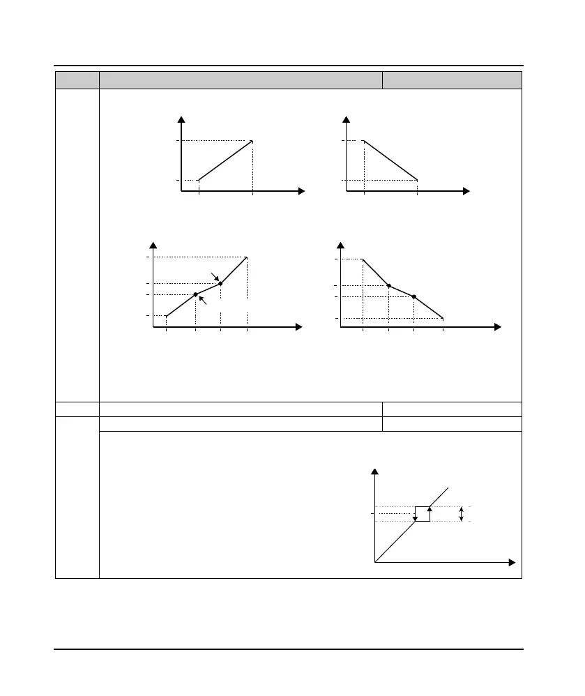
Picture:
• P is setting by terminal pulse, A is terminal analog reference.
• When P is 100% corresponds to the max. input pulse frequency defined by F16.17. When A is 100%, it
corresponds to 10V or 20mA.
F05.20 Hopping frequency range 0.00 - 30.00 [0.00Hz]
Hopping frequency setting can let converter output frequency avoid mechanical load resonance frequency
points.
• The inverter is prohibited to run at constant speed
within the skip frequency range, and the set
frequency will be automatically updated.
• When the set frequency skips, the output frequency
of the inverter does not suddenly change, but
changes smoothly according to the setting of the Acc.
/ Dec. curve.
• Skip frequency setting is invalid during process PID
control.
F05.01 F05.03
F05.04
F05.02
Setting
corresponding value
F05.01 F05.03
F05.02
F05.04
Setting
corresponding value
Positive and negative characteristic of line
P/A(setting) P/A(setting)
F05.15
F05.10
F05.12
F05.14
F05.16
F05.16
F05.14
F0
5.12
F05.10
F05.13 F05.11 F05.09 F05.15 F05.13 F05.11
F05.09
Positive and negative characteristic of polyline
Setting corresponding value Setting corresponding value
P/A(setting) P/A(setting)
Inflection point 2
Inflection point 2
Inflection point 1
Inflection point 1
Setting frequency after calculating
Setting frequency
F05.20
F05.17

 Loading...
