Shenzhen Hpmont Technology Co., Ltd. Chapter 7 Detailed Function Introduction
HD09-S Series User Manual V1.1 - 67 -
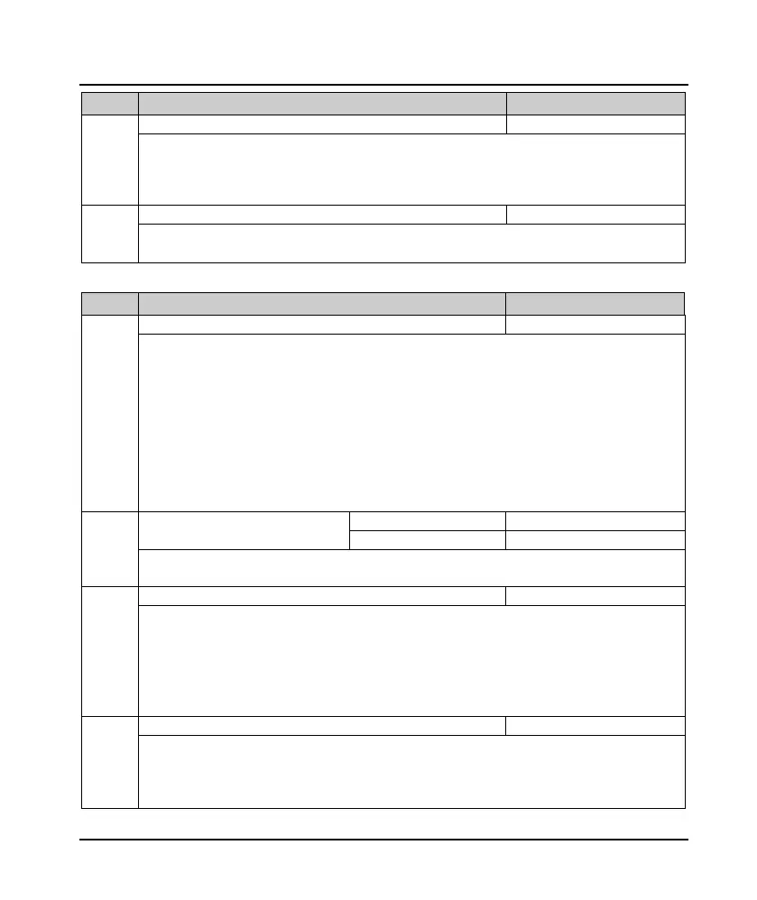
Ref. Code Function Description Setting Range [Default]
F19.21 Automatic current limit level 20.0 - 200.0 [150.0%]
The current threshold for the automatic current limiting operation is defined as the percentage relative to the
rated current of the drive.
• If the F19.21 setting is low when the automatic current limit is active, the inverter overload capacity may be
affected.
F19.22 Automatic current limiting integral time constant 0 - 1.000 [0.020]
F19.22 is set too small, can not effectively inhibit the output current increase;
F19.22 is set too large may cause the output frequency to fluctuate and cause the entire system to oscillate.
Other functions (F19.23 - F19.24, F19.44)
Ref. Code Function Description Setting Range [Default]
F19.23 Power-on instantaneous terminal detection 0,1 [0]
Valid only for 2-wire terminal control.
0: Rising edge effective.
• Suitable for use after power-on, in the absence of human intervention and does not allow automatic
operation, to prevent damage to equipment and protect personal safety.
• These situations need to be started when the inverter is powered on and the run command is completed.
1: Electrical level.
•
Suitable for ensured equipment and personal safety, in order to improve the automation and efficiency of
equipment, the need for the inverter to run immediately on power.
• In these cases, the drive will operate immediately as long as the command is setting to the terminal,
regardless of whether the run command is setting before the inverter is powered up or after power-up.
F19.24 Action voltage of brake unit 380V inverter: 630 - 750V [Type confirmed]
380 - 450V [Type confirmed]
Note: Only for drives with built-in brake unit that bleed energy through the braking resistor and that the energy
drain is only active when the drive is running.
Unit: Model 380V input voltage selection
• 0: 380 - 460V.
• 1: 260 - 460V.
• 2: 200 - 460V.
Ten: Model 220V input voltage selection
• 0: 200 - 240V.
• 1: 140 - 240V.
Note: Low voltage input, the inverter needs to derate the use, the actual output current does not exceed the rated
output current of the inverter.
Defines the display time of keypad LCD backlight when there is no operation.
• Normally on in 0. Normally on in fault.
• In no fault, more than F19.44 time, LCD backlight will be off. If any button press operation keypad at this
time, only to open the backlight and not execute the command.

 Loading...
