400 Series
EN - 50
CAUTION
If message “Measuring…” appears on the display, the instrument is
performing measurement. During this whole stage, do not disconnect the
test leads of the instrument from the mains.
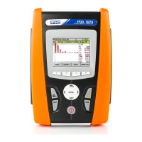
5. The instrument switches to
stand-by mode and displays
the screen reported here to
the side until the test lead
detects a voltage higher than
the minimum limit value
123
---
Waiting phase 1
Waiting for phase 1
1T
Func
6. When the instrument detects
a voltage higher than the
minimum limit value on the
test lead, the instrument
displays the screen reported
here to the side and starts
measuring the first voltage.
The instrument gives a long
acoustic signal until input
voltage is present
123
---
Measuring…
Measuring phase 1
1T
Func
7. Once acquisition is
completed, the instrument
switches to stand-by mode
and displays the screen
reported here to the side until
the test lead detects again a
voltage higher than the
minimum limit value
123
1--
Waiting phase 2
Waiting for phase 2
1T
Func
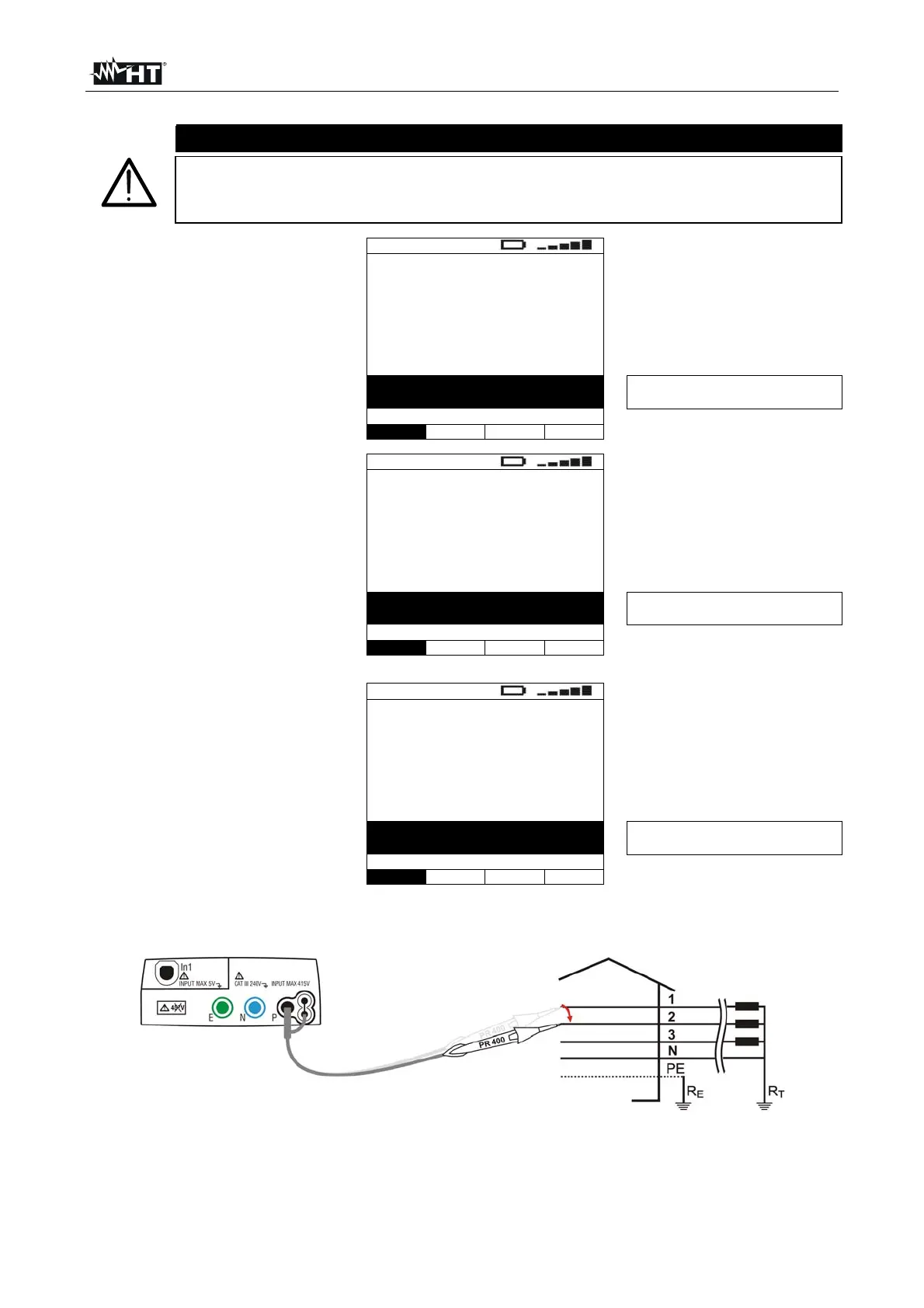
8. Move the black test lead to the second voltage of the sequence tested as in Fig. 26
and Fig. 27.
Fig. 26: Instrument connection for measuring the phase sequence with one lead, phase 2 connection

 Loading...