400 Series
EN - 51
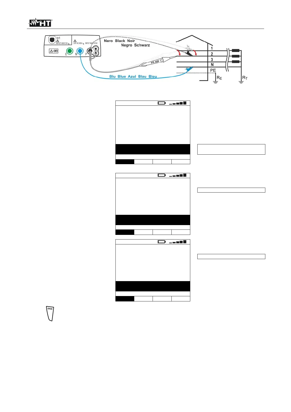
Fig. 27: Instrument connection for measuring the phase sequence with two leads, phase 2 connection
9. When the instrument detects
a voltage higher than the
minimum limit value on the
test lead, the instrument
displays the screen reported
here to the side and starts
measuring the second
voltage. The instrument
gives a long acoustic signal
until input voltage is present
123
1--
Measuring…
Measuring phase 2
1T
Func
10. Once acquisition is
completed, if the instrument
has detected a correct phase
sequence, it displays 123
and the message OK. It also
gives a double acoustic
signal
123
123
Correct phase sequence
OK
1T
Func
11. Once acquisition is
completed, if the instrument
has detected two voltages in
phase, it displays a screen
similar to the one reported
here to the side and gives a
double acoustic signal
123
11-
Phase conformity
OK
1T
Func
12.
The results displayed can be saved by pressing the SAVE key twice or the
SAVE key and, subsequently, the ENTER key (§ 8.1)

 Loading...


