GSC60
EN - 23
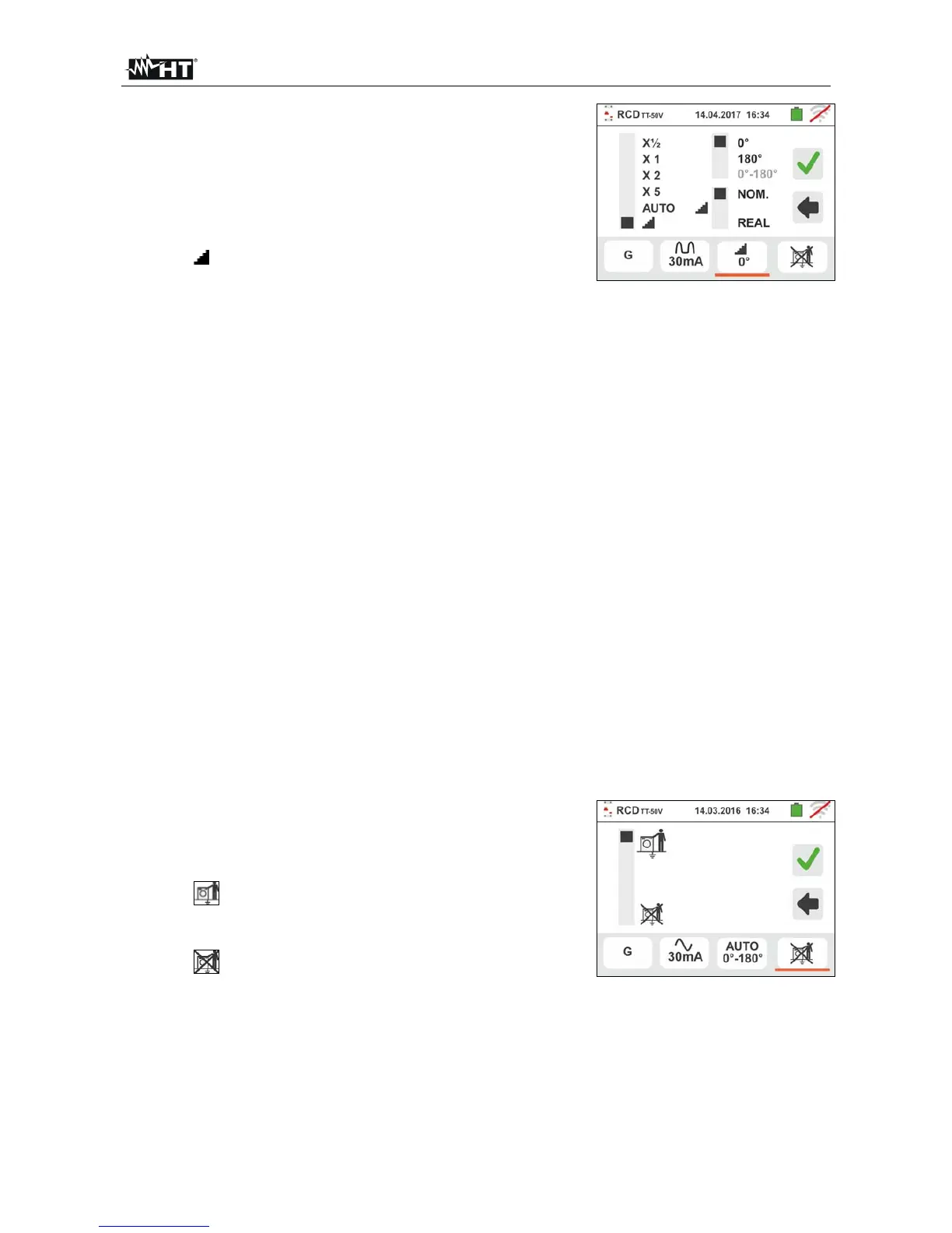
6. Touch the third icon at the bottom of display and
select the desired type of test among the options::
x ½ Manual with multiplier ½ Idn
x 1 Manual with multiplier 1Idn
x 2 Manual with multiplier 2Idn
x 5 Manual with multiplier 5Idn
AUTO Auto mode (6 tests in sequence)
Ramp (real tripping current measurement)
Move the right slide bar reference by selecting the
polarity of the test current between the options: 0°
(direct polarity), 180° (inverted polarity), 0°-180°
(for Automatic mode only). Move the lower right
slide bar reference by selecting (for Ramp mode
only) the kind of the trip out current visualization
between the followed options:
NOM the instrument shows the normalized
value of trip out current (referred to the nominal
current). Example: for RCD type A with
Idn=30mA the effective value of normalized trip
out current can be up to 30mA
REAL the instrument shows the effective
value of the trip out current by considering the
coefficients indicated by the IEC/EN61008 and
IEC/EN61009 guidelines (1.414 for RCD type
A, 1 for RCD type AC, 2 for RCD type B).
Example: for RCD type A with Idn=30mA the
effective value of trip out current can be up to
30mA * 1.414 = 42mA
NOTE: The selection of the two option involves
only the choose of the trip out current
visualization but not influence the outcome
test (OK/NO)
Confirm the choice by going back to the initial
measurement screen
7. Touch the fourth icon at the bottom of the display
and select the possible visualization of the contact
voltage value at the end of measurement. The
following options are possible:
The value of contact voltage is shown on
the display at the end of measurement (the test
time will be slightly longer)
The value of contact voltage is not
shown on the display at the end of
measurement. The symbol “- - -“ is shown
8. Insert the green, blue and black connectors of the three-pin shuko plug into the
relevant instrument input terminals B3, B4, B1. As an alternative, use the single cables
and apply the relevant alligator clips to the free ends of the cables. It is also possible to
use the remote lead by inserting its multipolar connector into the input lead B1.
Connect the shuko plug, the alligator clips or the remote lead to the electrical mains
according to Fig. 10, Fig. 12, Fig. 13, Fig. 14 and Fig. 15.