GSC60
EN - 81
8.
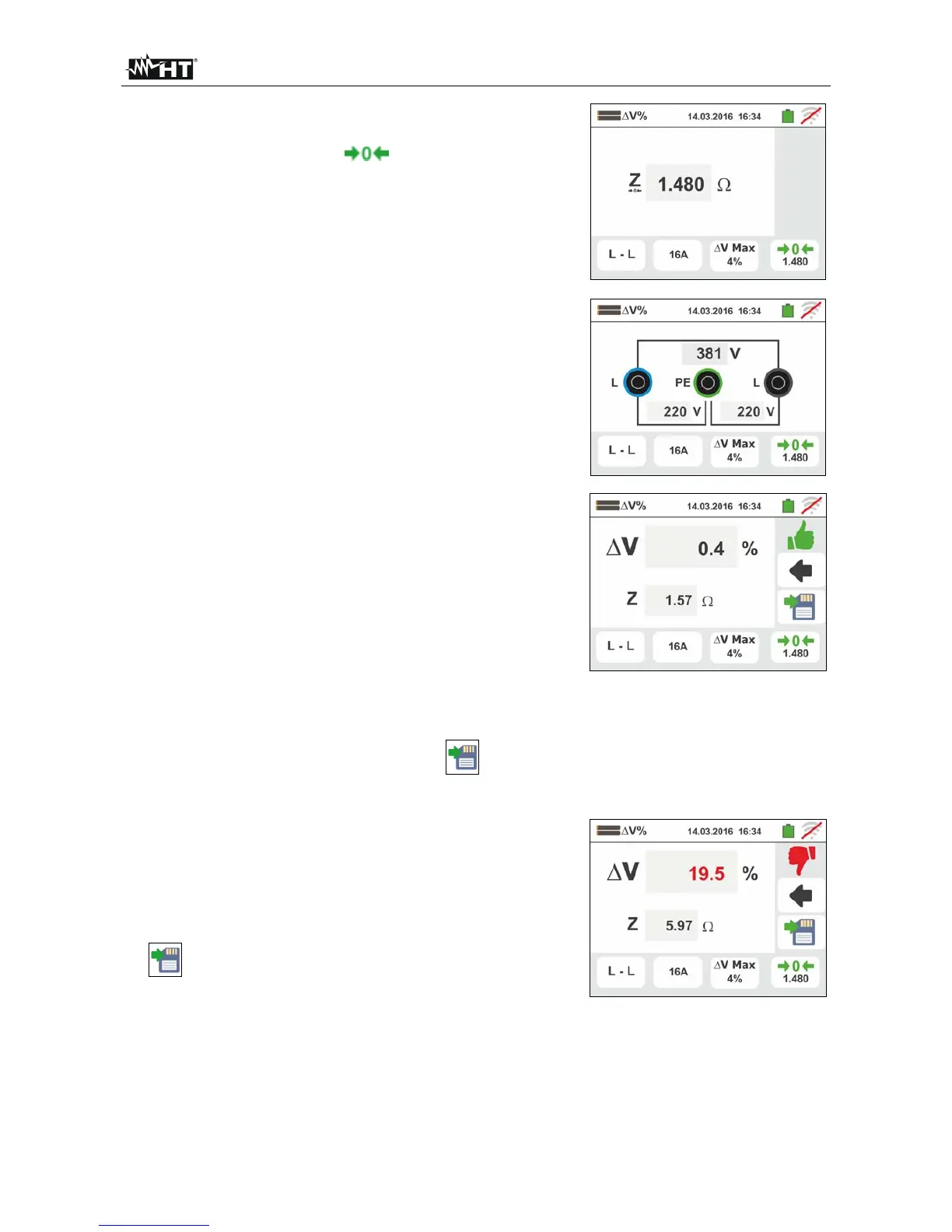
The value of Z1 (Offset) impedance is shown on the
display and is automatically included on the lower right
icon, together with the “ ” symbol to indicate the
instantaneous saving of the value
9. Connect the instrument to the final point of the main
line being tested according to Fig. 33 or Fig. 34 in order
to measure the Z2 impedance at the end of line. The
screen to the side is displayed. Note the previously
measured Z1 (Offset) value displayed
10
Press the GO/STOP key on the instrument to measure
the Z2 impedance and complete the V% voltage drop
measurement. During this whole stage, do not
disconnect the measuring leads of the instrument from
the system being tested
In case of positive result (maximum percentage value
of calculated voltage drop according to § 12.11 <
set limit value), the screen to the side is displayed by
the instrument, which contains the value of the Z2 end
of line impedance together the Z1 (Offset) value.
Press the SAVE button or touch the
icon to save
the measurement (see § 7.1)
11
In case of negative result (maximum percentage
value of calculated voltage drop according to §
12.11 > set limit value), the screen to the side is
displayed by the instrument, which contains the value
of the Z2 end of line impedance together with the Z1
(Offset) value. Press the SAVE button or touch the
icon to save measurement (see § 7.1)