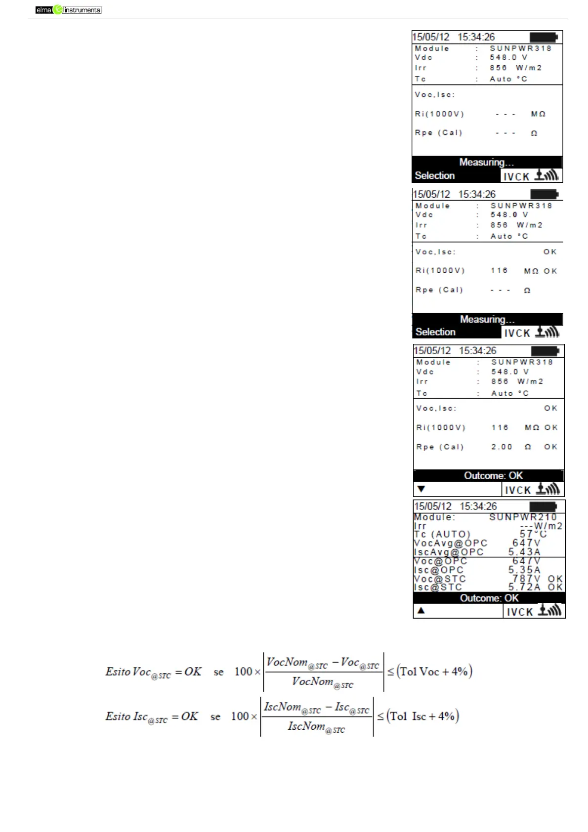
15. Press GO/STOP to start the test. In case no error conditions occur,
the instrument displays the message “Measuring…” and the
measure of open-circuit voltage between the terminals P and N and
of short-circuit current (for Isc values ≤ 10A).
16. When Voc and Isc measurements are complete, the message “OK”
is shown in case the result of the test is positive (measured values
within the tolerances set on the instrument)
17. With insulation measurement selected, the instrument goes on with
the test keeping terminals P and N short circuited, and carrying out
the test between this point and terminal E for the time necessary
to obtain a steady value.
18. The value of insulation resistance is shown in field “Ri” and the
message “OK” appears in case the result of the test is positive
(measured value higher than the minimum limit value set on the
instrument).
19. With continuity measurement selected, the instrument goes on by
opening the short- circuit and carrying out the test between
terminals E and C.
20. The value of resistance in the continuity test is shown infield “Rpe”
and the message “OK” appears in case the result of the test is
positive (measured value lower than the maximum limit value set
on the instrument).
21. The message “Outcome:OK” is finally shown by the instrument in
case the result of all performed tests is positive
22. Press the arrow key to show the following page in which the
values of parameters Voc and Isc are shown. It shows:
The module being used
The value of irradiance
The value of temperature of the module
The average values of Voc and Isc under OPC
The values of Voc and Isc measured under OPC
The values of Voc and Isc calculated under STC and the
relevant partial results obtained by comparison with
the
nominal values.