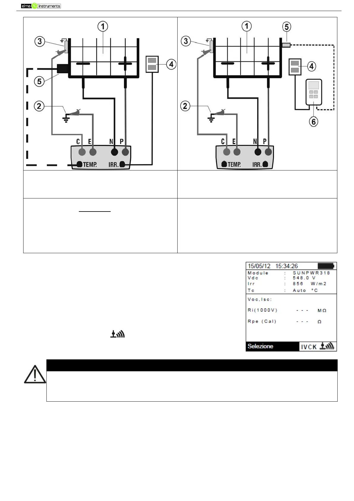
Fig. 8: Connection for IVCK test with direct
irradiance measurement
o
Fig. 9: Connection for IVCK test with irradiance
measurement through SOLAR-02
CAPTION:
E: Green cable
C: Blue cable
P: Red cable
N: Black cable
1. PV module/string
2. Main system earthing
3. Earthed metal structure in the system
4. Reference cell for irradiance measurement
5. Temperature sensor (if required)
6. Remote unit SOLAR-02
14. In the initial screen of IVCK mode, the following values are
displayed in real time:
Module type of module being tested
Vdc value of output voltage from module/string
Irr irradiance (from a direct measurement or SOLAR-02
connected via RF)
Tc modulo temperature (in MAN or AUX mode) and the
relevant measuring mode, or “- - -” in AUTO mode
In case, the symbol “ ” of RF connection with
SOLAR-02
Upon pressing the GO/STOP key, different error messages can be displayed by the
instrument (see § 6.6) and, therefore, the test cannot be started. Check and eliminate, if
possible, the problem causing the error message before going on with the test.