43
Schematic diagram
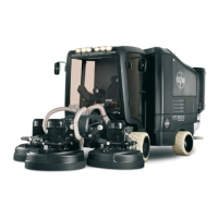
Suction system
No. Function:
1 Grinding cover. The grinding dust is vacuumed up
here.
2 Hose for transporting grinding dust.
3 Collection hose for transporting grinding dust.
4 Valve
5 Pre-separator that takes care of coarse grinding
residue.
6 The lter cyclone takes care of ne grinding dust.
7 The air cannon/lter cleaner produces pulses of
compressed air to clean the lter cyclone’s lter.
8 Absolute lter which cleans the remaining air of par-
ticles.
9 Suction fan.
10 Exhaust after suction fan.
1
2
3
4
5
6
7
8
9
10