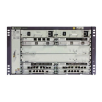
Figure 3-4 Slot layout of the CX600-X2-M16
23
FAN
21 PSU 22 PSU
11 SIC 12 SIC
10 SIC
9 SIC
18 NSU
17 NSU
3 SIC 4 SIC
2 SIC1 SIC
19 MPU 20 MPU
15 SIC 16 SIC
14 SIC
13 SIC
7 SIC 8 SIC
6 SIC5 SIC
Table 3-1 Slot layout of the CX600-X2-M16
Slot Numb
er
Remarks
1 to 16 16 For PICs, which include HICs, FICs and the other subcards.
NOTE
Other subcards, including the 8-Channel CWDM Multiplexing/
Demultiplexing Physical Interface Card and Auxiliary Flexible
Interface Card, can be installed in any slot numbered 1 to 16.
17 and 18 2 For NPUs.
19 and 20 2 For MPUs, which are in 1:1 backup.
21 and 22 2 For PSUs, which are in 1+1 backup.
23 1 For the fan frame.
Table 3-2 Slot layout with the NPU-50\50-E
Slot Type Remarks
1 to 4 FIC Include FICs and the other subcards
Such as 32-Port E1 Physical Interface Card, 4-Port OC-3c/
STM-1c POS-SFP Physical Interface Card
HUAWEI CX600-X1-M/CX600-X2-M Series Metro
Services Platform
Hardware Description 3 CX600-X2-M16 Hardware Description
Issue 03 (2014-04-30) Huawei Proprietary and Confidential
Copyright © Huawei Technologies Co., Ltd.
63
 Loading...