PCIe
Device
CPU PCIe
Standard
Connecto
r
Bandwid
th
Bus
Width
Port
Number
Slot Size
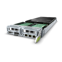
Mezzanin
e card 2
CPU 2 PCIe 3.0 Two x16 Two x16 Port 3A
(through
PCIe
switch)
Non-
standard
device
NVMe
SSD 2
CPU 1 PCIe 3.0 x4 x4 Port 2C 2.5-inch
disk
NVMe
SSD 3
CPU 1 PCIe 3.0 x4 x4 Port 2A 2.5-inch
disk
NVMe
SSD 4
CPU 1 PCIe 3.0 x4 x4 Port 2B 2.5-inch
disk
NVMe
SSD 5
CPU 2 PCIe 3.0 x4 x4 Port 2A 2.5-inch
disk
NVMe
SSD 6
CPU 2 PCIe 3.0 x4 x4 Port 2D 2.5-inch
disk
NVMe
SSD 7
CPU 2 PCIe 3.0 x4 x4 Port 2C 2.5-inch
disk
NOTE
NVMe SSDs 2 to 4 are connected to CPU 1, and NVMe SSDs 5 to 7 are connected to CPU 2. It is
recommended that NVMe SSDs are evenly installed to ensure bandwidth balance.
Table 2-4 GP608 PCIe slot description
PCIe
Device
Mezzani
ne Card
Channel
PCIe
Standard
Connecto
r
Bandwid
th
Bus
Width
Port
Number
Slot Size
PCIe slot
1
Channel 2
of
mezzanine
card 1
PCIe 3.0 x16 x16 - Full-
height
full-length
dual-width
card
PCIe slot
2
Channel 2
of
mezzanine
card 1
PCIe 3.0 x16 x16 - Full-
height
full-length
dual-width
card
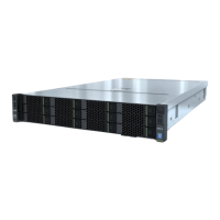
FusionServer G5500 Server
User Guide
2 Components
Issue 02 (2017-12-15) Huawei Proprietary and Confidential
Copyright © Huawei Technologies Co., Ltd.
23