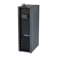
Figure 5-28 Optical cable positions at the bottom
(1) DC power cable hole (2) AC input power cable or ground cable hole
(3) Optical cable or network cable hole (4) UPS or RS485 cable hole (reserved)
Figure 5-29 Connecting FE communications cables
(1) White-and-orange
(2) Orange (3) White-and-green (4) Blue
(5) White-and-blue (6) Green (7) White-and-brown (8) Brown
Step 4 Bind the cables.
Step 5 Install the removed cover.
LUNA2000-2.0MWH Series Smart String ESS
User Manual 5 Installing Cables
Issue 08 (2022-11-15) Copyright © Huawei Technologies Co., Ltd. 132
 Loading...


