EasyManua.ls Logo

Hunter DSP9200 Series User Manual

Hunter DSP9200 Series
70 pages
To Next Page IconTo Next Page
Page #1 background imageLoading...
Page #1 background image
OPERATION INSTRUCTIONS Form 5473-T, 01-10
Supersedes Form 5473-T, 09-08
DSP9200 Series
Wheel Balancer
© Copyright 2006 -2010 Hunter Engineering Company

Table of Contents

Question and Answer IconNeed help?

Do you have a question about the Hunter DSP9200 Series and is the answer not in the manual?

Hunter DSP9200 Series Specifications

General IconGeneral
BrandHunter
ModelDSP9200 Series
CategoryScales
LanguageEnglish

Summary

Getting Started

Safety Hazard Definitions

Outlines safety precautions and defines hazard symbols (Caution, Warning, Danger).

Important Safety Instructions

Electrical and Power Requirements

Electrical Specifications and Warnings

Details voltage, amperage, grounding, and safe electrical practices for the DSP9200.

Decal Information and Placement

Unit Power and Initial Setup

Specific Power Source Precautions

Details power requirements, grounding, and plug specifications for the DSP9200.

DSP9200 Component Identification

Key Component Locations

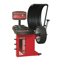
Identifies key parts of the DSP9200 balancer with labels in a diagram.

Operating the Control Panel

Control Panel Layout and Indicators

Identifies and describes the function of each button and display on the control panel.

Using Control Panel Buttons

Explains how to use the various buttons for different procedures and selections.

Using Wheel Dimension Control Knobs

Balancing Overview Concepts

Balancing Modes Explained

Introduces static and dynamic balancing concepts.

Understanding Dynamic Imbalance

Identifying Dynamic Balance Weight Planes

Wheel Mounting Methods

Balancing a Wheel: Initial Steps

Mounting the Wheel on the Spindle Shaft

Details the initial steps for mounting a wheel onto the balancer shaft.

Front/Back Cone Mounting Technique

Cone and Flange Plate Mounting

CenteringCheck® Procedure

Measuring Wheel Dimensions

Auto Dataset® Arm Measurement

Explains using Auto Dataset® arms for automatic rim measurement.

Measuring for Mixed/Adhesive Weights

Manually Setting Wheel Dimensions

Locating Wheel Weights at TDC and BDC

Standard Balancing Procedures

Standard Balancing with Clip-on Weights

Step-by-step guide for performing standard balancing using clip-on weights.

Static/Standard Balancing with Clip-on Weight

Adhesive Weight Procedures

Measuring Dimensions for Adhesive Weight Placement

Static/ALU Balancing with Adhesive Weight

Optimizing Tire & Wheel Imbalances

OPT-1: Wheel with Tire Mounted Procedure

Procedure for optimizing tire and wheel imbalance with the tire mounted.

OPT-2: Tire Not Mounted Procedure

Patch Balance Procedures

Static Patch Balance (Single Weighted Patch)

Details static patch balancing using a single weighted patch.

Dynamic Patch Balance (Two Weighted Patches)

Dynamic Patch Balance with Two Adhesive Weights

Balancing Features and Options

Locating Adhesive Weights with Dataset Arm

Spindle-Lok® and Related Features

Display Settings and Weight Splitting

Split Weight® Operation Guide

Split Spoke® Feature

Placing Hidden Weights Forward of Obstructions

Automatic Weight Recalculation and Data Storage

Maintenance and Calibration

Calibration Procedures

Calibration Procedures Overview

Outlines the steps for calibrating the balancer.

Detailed Balancer Calibration Steps

Inner Dataset® Arm Calibration Procedure

Inner Dataset® Arm Calibration Steps

Outer Dataset® Arm Calibration Procedure

Related product manuals