Show Details
The net tire pull results of all alternate placements appear in a table on the summary
printout and can be viewed on-screen by pressing the “Show Details” softkey on the
second row of softkeys.
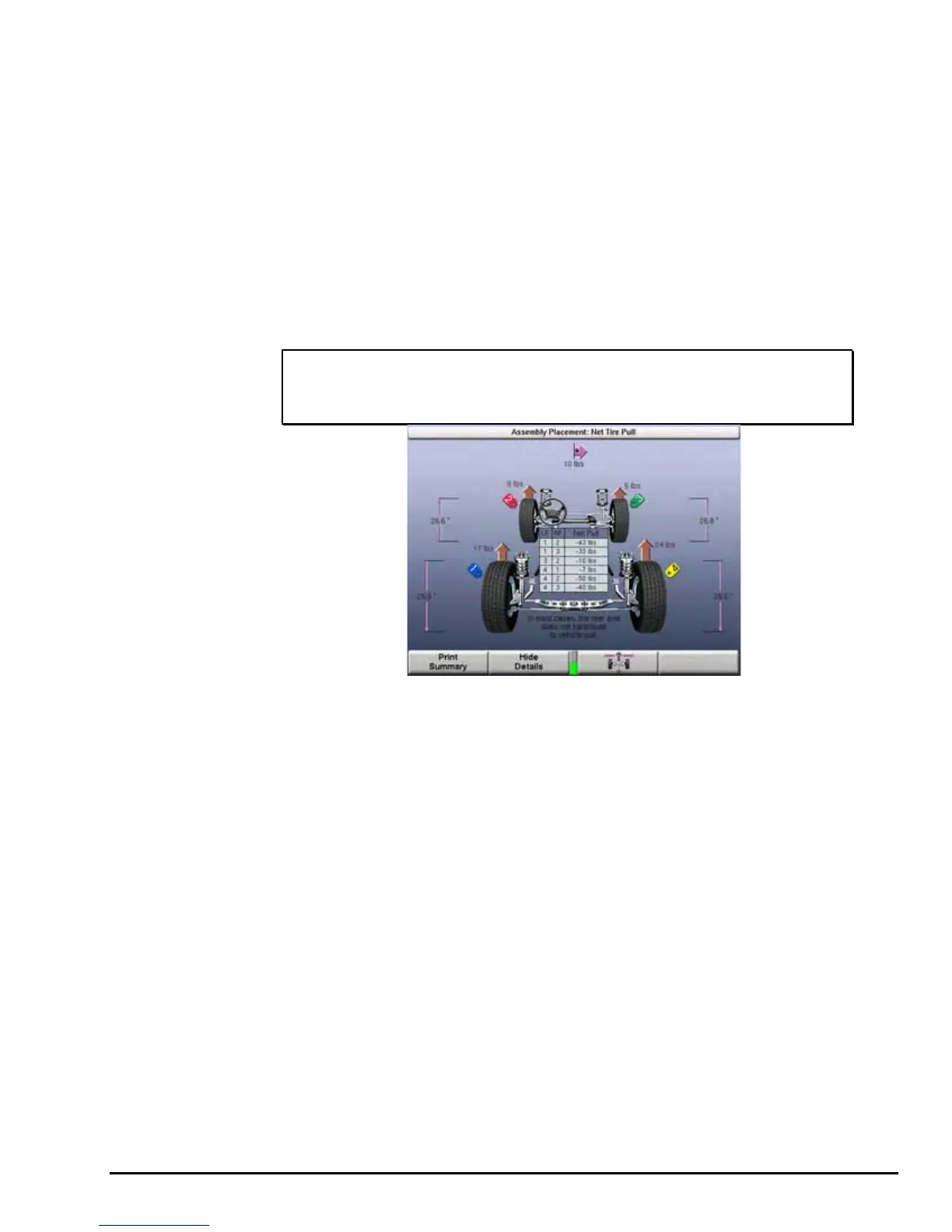
The following example shows a case where the “Show Details” softkey can help. With
the tire/wheel assemblies positioned as recommended to provide least pull, a
vibration could be induced, due to the large amount of radial force in tire/wheel
assembly 4. By pressing “Show Details,” the net tire pull results of all alternate
placements appear in a table. Using this “Details” table, look for the lowest value of
net pull that does not use tire/wheel assembly 4 on the front axle. According to the
table, placing tire/wheel assemblies 2 on the left and 3 on the right, a net pull of 10
pounds to the right would result. This placement would yield only a slightly higher net
pull, however would minimize vibration by positioning tire/wheel assembly 4 opposite
the driver on the rear axle.
NOTE: The table shows the same combinations that can be viewed
by repeatedly pressing the “Show Alternate Placements”
softkey.
Determining Tire Conicity Outliers
Locating one or more tires with a large difference in conicity may be achieved by
using the “Show Details” graph. Locate one or more outliers by looking for high net
pull examples when mixing tires.
Printout
The printout serves both the technician and the customer. If the GSP9720JLR is not
equipped with a printer, it is recommended that the technician copy the information
provided on the screen for reference. Keeping a record during service of the vehicle
will allow the technician to be able to change tire/wheel positions after the “Vehicle
Plan View” is reset.
If the GSP9720JLR is equipped with a printer, press “Print Summary” to print the
summary.
By printing the summary, the technician has a printed reminder of where to position
each tire/wheel assembly on the vehicle to minimize the effects of lateral force. If the
desired results are not evident during a test drive, the technician may refer to the
alternate placements shown on the printout, without the need to repeat the entire
procedure.
The printout can be used to explain the effects of lateral force and the steps taken to
reduce their adverse effect to the customer.
GSP9720JLR Wheel Balancer Operation Instructions Road Force® Measurement Procedures
101
 Loading...


