2.10
CUTTING PARAMETERS CHART
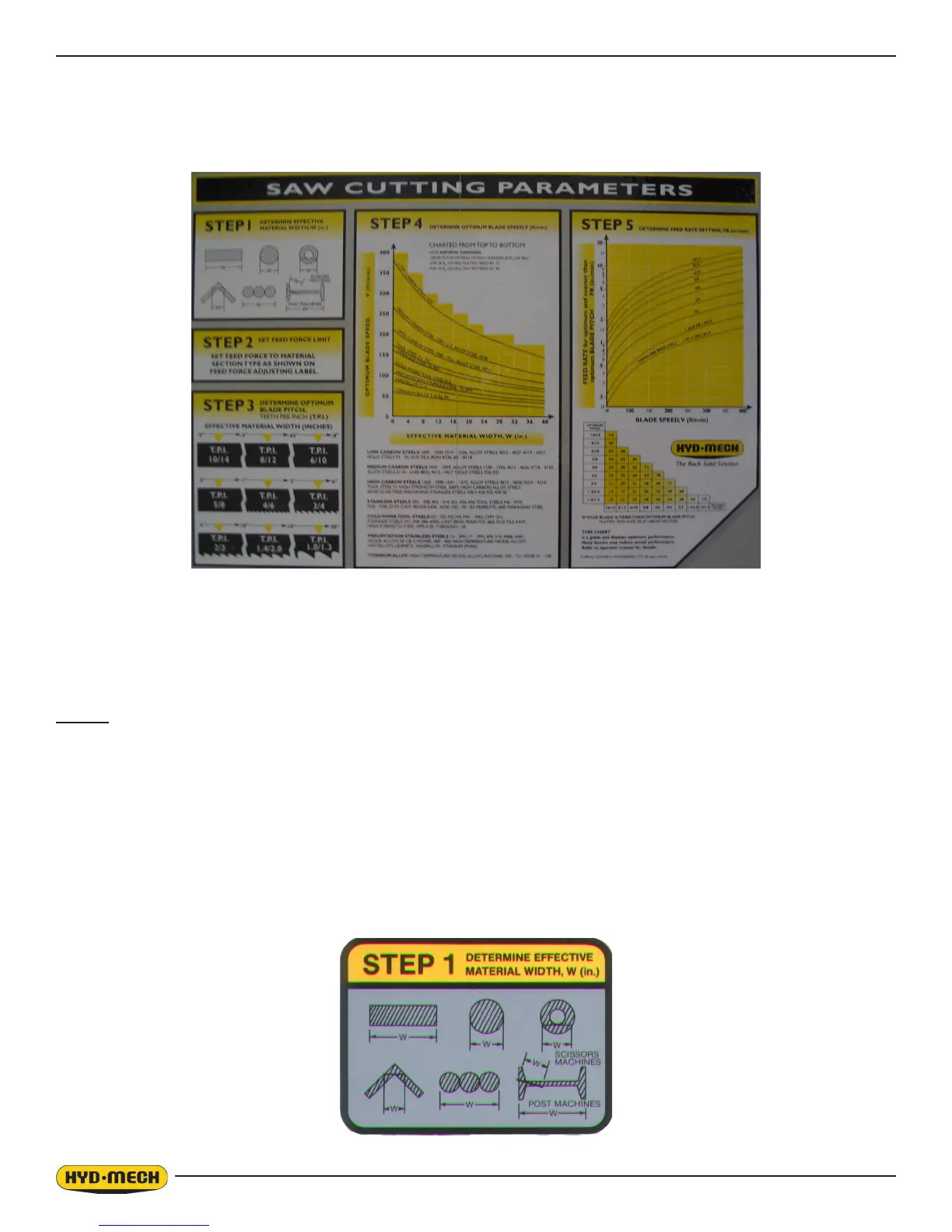
A full size CUTTING PARAMETERS CHART is mounted on the drive door of the saw. The chart contains ve steps for the
operator to follow in order to achieve optimum performance of the saw. Examples of the correct use of this chart are on
the following pages.
CHART EXAMPLE #1
We will use the parameters chart to set up the saw for cutting 8” (200mm) diameter #1045 Carbon Steel.
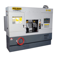
STEP 1 - DETERMINE EFFECTIVE MATERIAL WIDTH (w) (INCHES) OR (mm)
Effective material width W (in.) for most common shapes of materials is the widest solid part of the material to be in con-
tact with blade during cutting. For simple shapes, as illustrated on the chart, this can be directly measured. For bundles of
tubes and structurals, measuring the effective width is difcult. Effective width is 60% to 75% of the actual material width.
NOTES:
1. Both effective material width and guide arm width are used in setting the saw.
2. Guide arm width is the distance between the guide arms and is used in STEP 2.
3. Effective material width, as determined here in STEP 1, can be considered as the average width of material
“seen” by each tooth, and it is used in STEPS 3 and 4. In Example #1, for an 8” (200mm) diameter solid, Effective
Material Width is 8” (200mm).