2.15
ADDITIONAL CUTTING SETUP EXAMPLES
EXAMPLE #2
Material - Round Steel Tube SAE 4320 hardened to 35 RC (325 Bhn)
Dimensions - 6” O.D. x 4” I.D. (150 mm O.D. x 100mm I.D.)
1. Effective Material Width 4 ½ “ (.75 x 6) or 114mm (19 x 6).
2. Feed Force limit setting for 6” diameter material - refer to feed force limit setting in Step 2.
3. Optimum blade pitch (TPI): ¾ TPI. Actual blade pitch on the saw: 4/6 TPI.
4. Optimum blade speed for 4 1/2 “ effective 225 ft/min (70m/min) material width. Blade speed reduced by
hardness factor: 225 ft/min x .60 = 135 ft/min or 70m/min x .60 = 42m/min.
5. Feed Rate for ¾ TPI blade is 1.8 in/min (45mm/min). Feed Rate for 4/6 TPI blade is 1.8 in/min x .70 =
1.3in/min (reduced by ner than optimum blade pitch factor) or 45mm/min x .70 = 31.5mm/min.
EXAMPLE #3
Material - Bundle - Low carbon steel 2” x 2” tube with ¼” wall, 12 piece bundle (50 mm x 50mm with 6mm wall)
Dimensions - 6” x 8” (150mm x 200mm)
1. Effective material width: 5” (.6 x 8”) or 120mm (.6 x 200).
2. Feed force limit setting for 8” diameter material. Refer to Feed Force Limit setting in Step 2.
3. Optimum blade pitch (TPI): ¾ TPI.
4. Optimum blade speed for 5” effective material width: 320 ft./min. (100m/min).
5. Feed Rate for ¾ TPI blade: 4.0 in/min or 100mm/min.
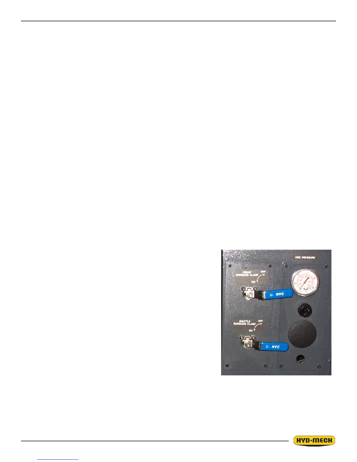
OTHER HYDRAULIC CONTROLS (OPTIONAL)
Bundling Clamp Valves
The bundling clamps can be used to supplement the front and shuttle vises
by clamping down on the work piece from above. As the name implies,
they are particularly used to clamp work pieces made of bundles of smaller
material.
For simple, non-bundled work pieces, the bundling clamps are not usually
needed.
Each bundling clamp has its own control valve. When the control valve
lever is positioned horizontally the bundling clamp is locked in its current
position. When the valve lever is vertical, the bundling clamp will move
open and shut with its associated vise.
Vise and Bundling Clamp Speed Adjustment
Vise and bundling clamp speed is factory preset to synchronize movement
of both clamps. The tuning valves are located next to the plate holding the
bundling control valves. Valves can be accessed through the hydraulic power pack door opening. Information on valve
adjustment is provided on the hydraulic plumbing diagram in Section 5.