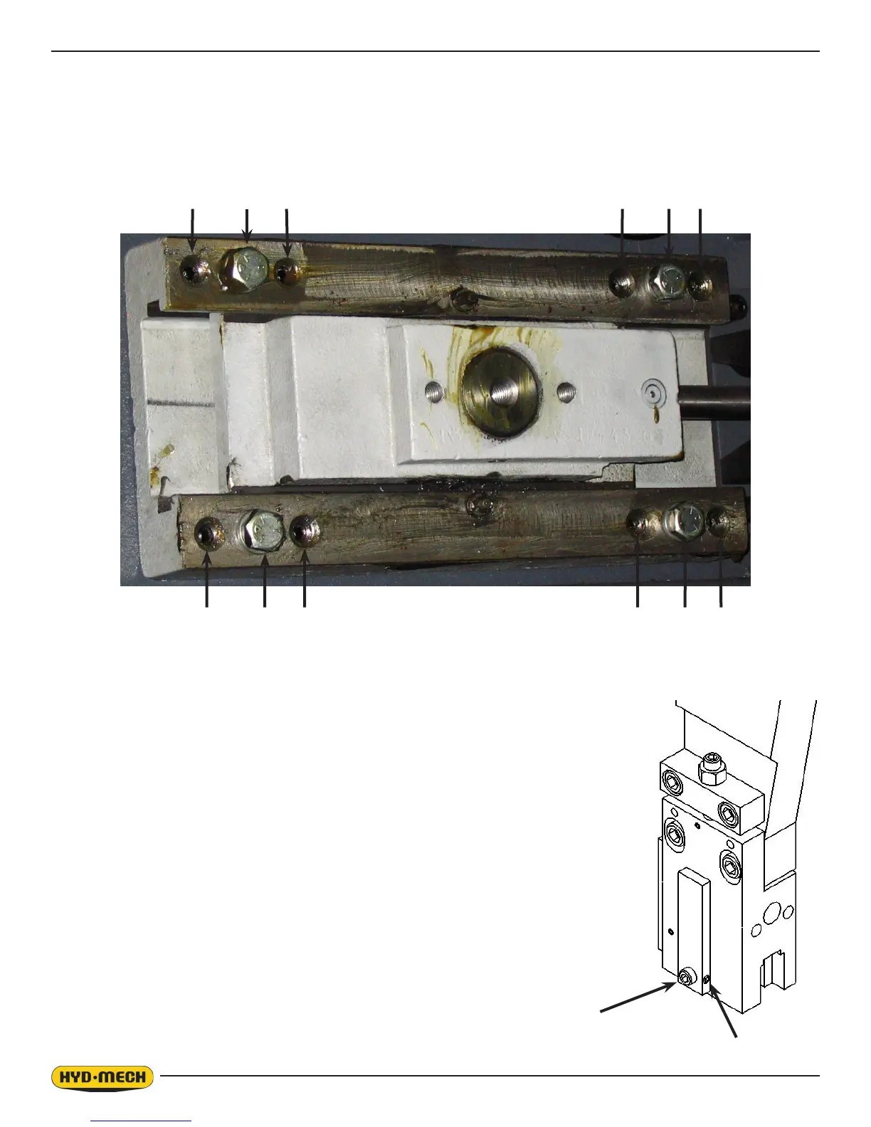
3.4
IDLER WHEEL ADJUSTMENT
The tracking is adjusted by regulating the “push” set screws and the “pull” hex bolts. Before making any adjustments, bolts
“A & B” should be loosened but remain snug. This will allow easy movement for the slide assembly. Loosening bolts “A”
and turning in set screws “C” by equal amounts will move the blade off the wheel. Loosening bolts “B” and turning in set
screws “D” by equal amounts will move the blade onto the wheel. After each “C” and “D” adjustment, tighten bolts “A” and
“B”, run the blade and then check the tracking.
BLADE GUIDE ADJUSTMENT
Both guide arms are provided with blade guide assemblies consisting of carbide pads that
are integral to the correct guidance of the saw blade. These guide assemblies will require
an adjustment periodically; refer to Troubleshooting in this section for indications that
adjustment is needed. To adjust the pads properly, follow this simple procedure. With the
lever in the locked position, loosen the small set screw “A” in the edge of the lever. Turn the
adjusting set screw “B” clockwise until tight and then loosen it 1/8
th
of a turn. With the lever
still in the locked position, tighten the small set screw in the side of the lever. This should
put just enough pressure on the blade to permit you to push the blade out approximately
1/8”.
In the event that the pads must be replaced, refer to the exploded parts drawing in Section
6.
D
D
C C
A
A
C
B
C B
D
D
B
A