MAINTENANCE
8-20 HySpeed HT2000 Instruction Manual
19
8. If chopper still does not output 280V after completing step 7, there may be a problem with the control
signal or the chopper module. The chopper drive signal comes through the analog board PCB3 as an
analog level from 0 to +8 VDC, which varies the duty cycle and subsequent output current of the chopper.
These analog signals are on pins 3&4 REC1 of PCB3 for CH1, and 5&6 REC1 for CH2.
To determine if there is a problem with the chopper modules or with control board PCB2 or analog board
PCB3, proceed as follows:
• Ensure that high frequency is still disabled (see step 1).
• Disconnect PL3.1 from REC1 on PCB3.
• Place voltmeter across output of chopper and press the START command.
• If the voltmeter reads +280 VDC, then replace either control board PCB2 or analog board PCB3.
• If the voltmeter reads 0 volts, then replace corresponding chopper module CH1 or CH2.
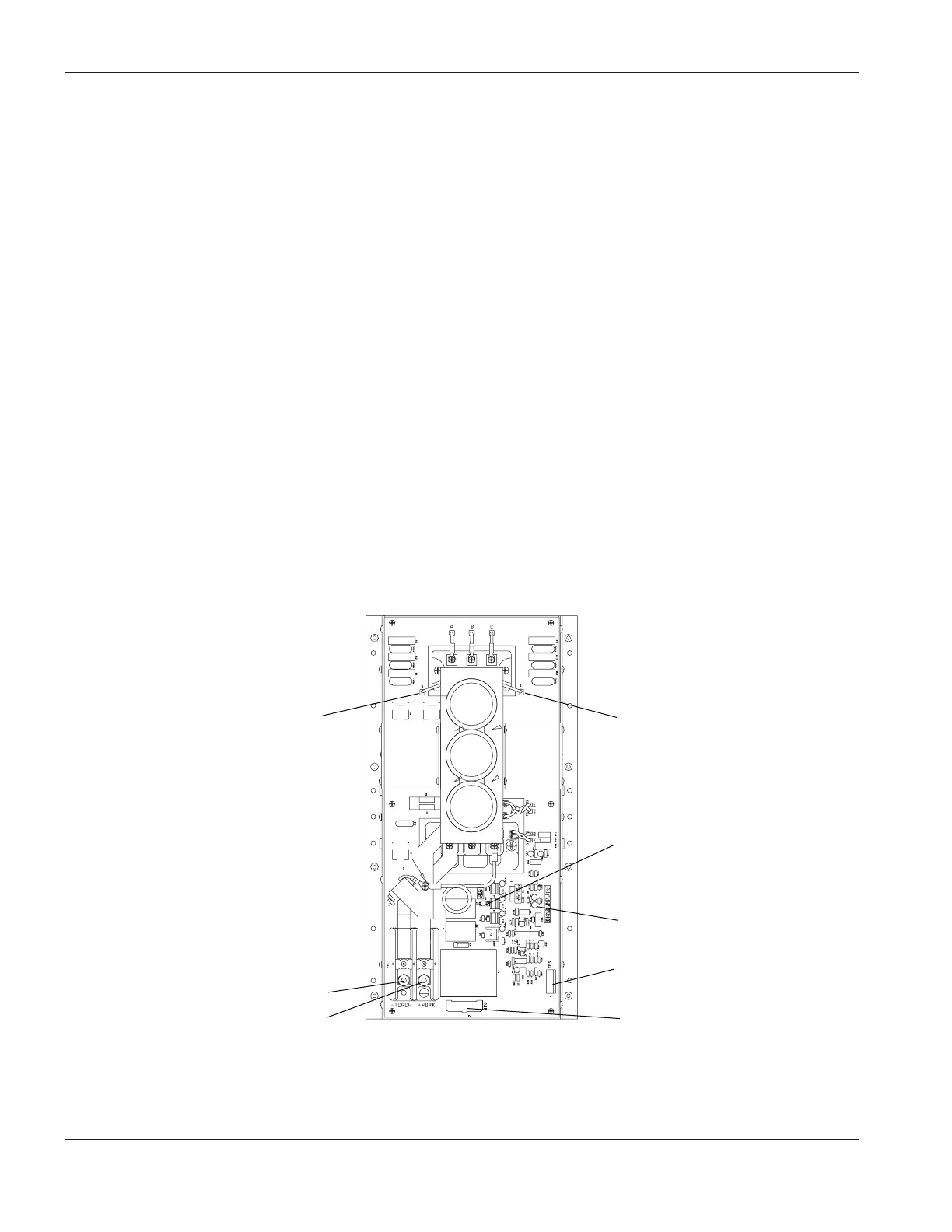
Figure 8-3 Chopper Module – Front View
Bridge (+)
- TORCH
+ WORK
Bridge (–)
LED3
LED1
JP9
JP6