Component replaCement
6-4 powermax
45
Service Manual
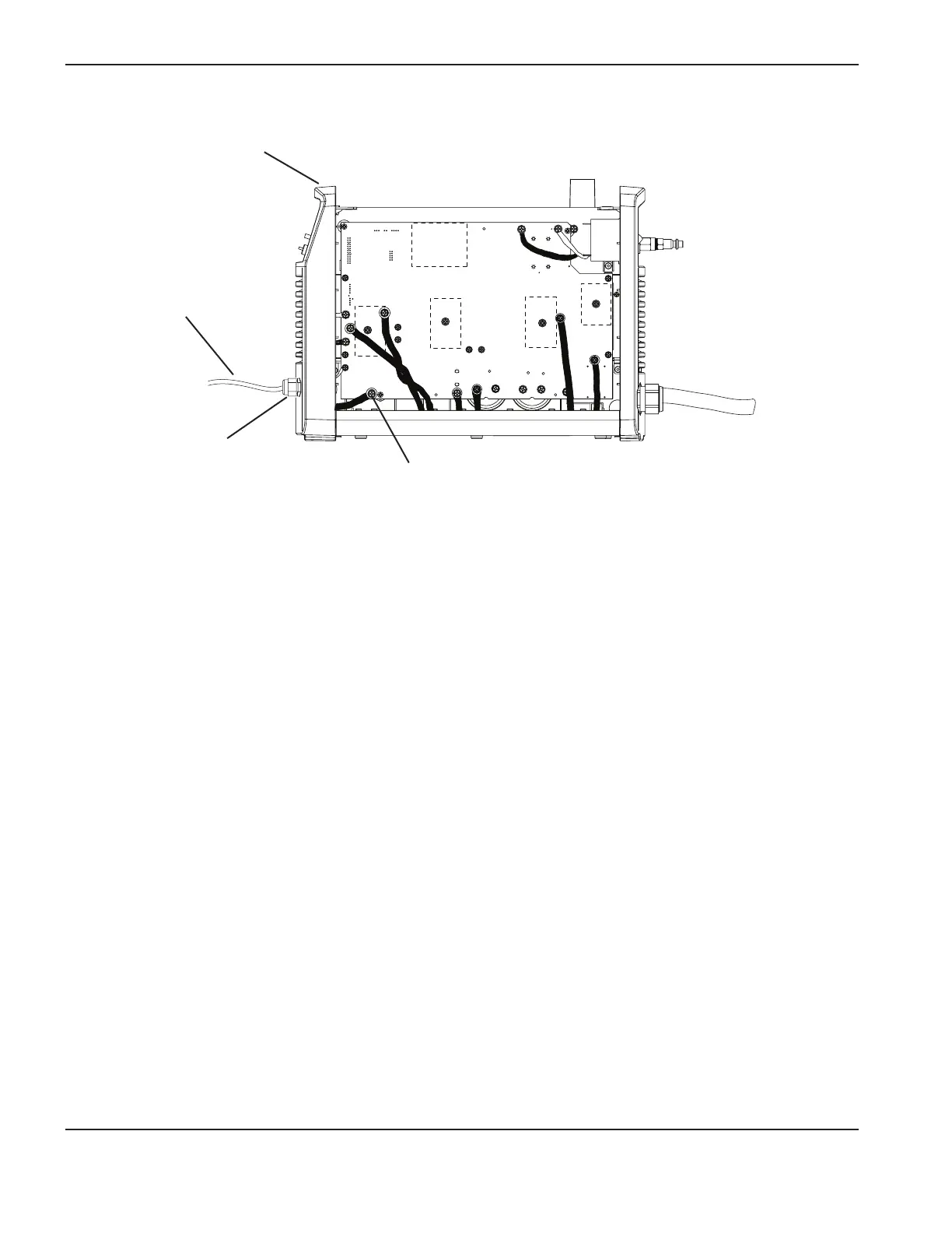
5. Thread the connector end of the new work lead through the front panel and fit the strain relief into the hole in the
panel.
6. Slide the nut over the work lead’s connector. Gently tilt the front panel away from the power supply and screw the
nut onto the strain relief.
7. Attach the work lead to the power board at J21 using the screw that you removed earlier. The torque setting for
this connection is 23.0 kg cm (20 inch-pounds).
8. Realign the front panel.
9. Replace the Mylar barrier and slide the cover back onto the power supply. Position the handle over the holes in the
top of the cover, then secure the cover with the 2 screws.
10. Reconnect the electrical power and the gas supply.
TP 19
W
-
+
-
+
TP 18
R
TP 17
B
192 VDC
192 VDC
Work lead
Work lead connection to power board (J21)
Front panel
Strain relief