TroubleshooTing and sysTem TesTs
powermax
45
Service Manual 5-21
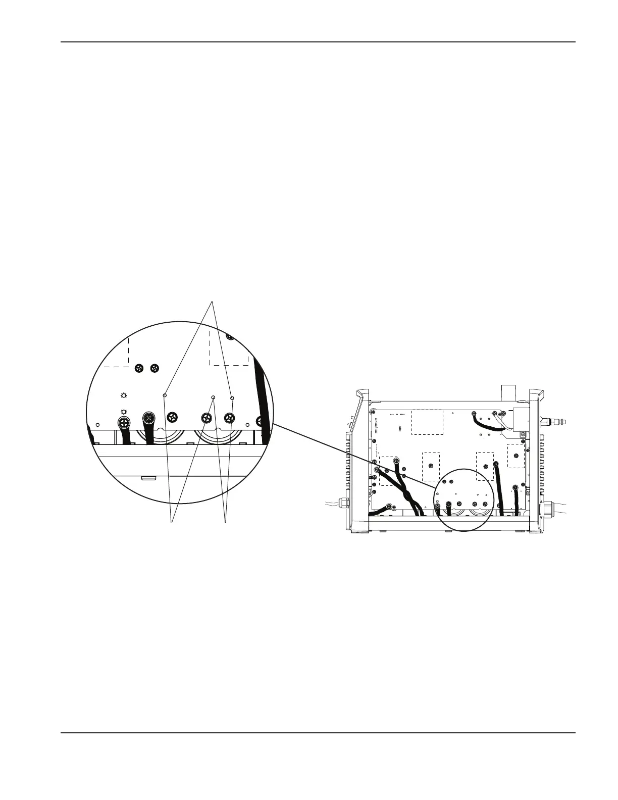
Test for 200–240V CSA and 230V CE power supplies
1. Turn OFF the power.
2. Position the multimeter leads to measure the boosted bus voltage on the power board by attaching the test leads
to TP (test point)19 and TP18. Turn on the power. The multimeter should read 385VDC. If you get a value other
than 385VDC, multiply the reading by 0.00601. Compare that value to a reading at pin 21 on J7. They should
have the same value.
3. Turn the power OFF. Attach the E-ZHooks to TP19 and TP17. Turn the power ON after you have connected the
multimeter. This value should be 192.5VDC or one-half of whatever value you found in step2.
Note: All values can be ±10%.
4. Turn the power OFF and move the E-Z Hooks to TP18 and TP17. Turn the power ON after you have connected
the multimeter. This value should be 192.5VDC or one-half of whatever value you found in step2.
5. The values found in steps3 and4 should be approximately equal. If they differ by more than 30V, replace the
power board.
TP 19
W
-
+
-
+
TP 18
R
TP 17
B
192 VDC
192 VDC
TP 19
W
-
+
-
+
TP 18
R
TP 17
B
192 VDC
192 VDC
Step 3
Step 4
Step 2