TroubleshooTing and sysTem TesTs
powermax
45
Service Manual 5-23
Test for 480V CSA power supplies
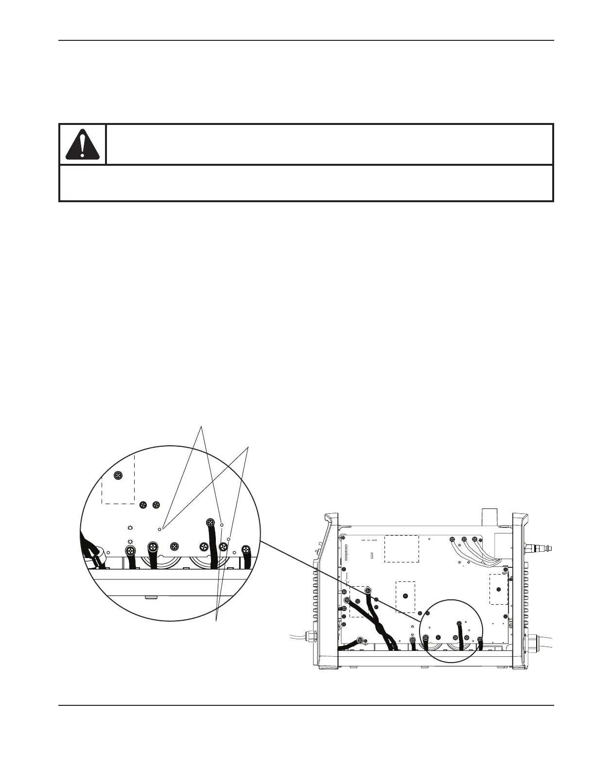
For this test, you can use the test point loops or you can test on the capacitor screws. The test points are labeled on the
back of the power board, as are the voltages and positive and negative capacitor terminals.
CAUTION
To test using the test points, do not use a multimeter with test probes. Use E-Z Hook leads instead
and attach them to the test point loops.
1. Turn OFF the power.
2. Position the multimeter leads to measure the voltage on the power board by attaching the test leads with the
negative lead on TP17 and the positive lead on TP16. Turn on the power. The multimeter should read 670VDC.
If you get a value other than 670VDC, multiply the reading by 0.003. Compare that value to a reading at pin21 on
J8. They should have the same value.
3. Attach E-Z Hooks to TP (test point)17 and TP18. Turn the power ON after you have connected the multimeter.
This value should be 335VDC or one-half of whatever value you found in step2.
Note: All values can be ±10%.
4. Turn the power OFF and move the E-Z Hooks to TP18 and TP16. Turn the power ON after you have connected
the multimeter. This value should be 335VDC or one-half of whatever value you found in step2.
5. The values found in steps3 and4 should be approximately equal. If they differ by more than 30V, replace the
power board.
TP17
W
+
-
+
-
TP18
B
TP16
R
~280 VDC
~280 VDC
TP17
W
+
-
+
-
TP18
B
TP16
R
~280 VDC
~280 VDC
Step 2
Step 4
Step 3