Service Manual
(3) TVO SWITCH: This interface is used to supply power to the TX VCO.
(4) RX LO OUTPUT: This interface is used by the RX LO to output signal to the RX mixer.
(5) TX LO OUTPUT: This interface is used by the TX LO to output signal to the Cartesian IC.
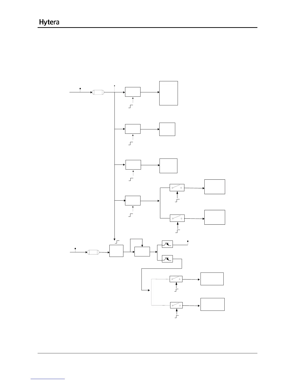
1.5 Power Supply Module
3V3D
60R
3V3_RF
LDO
Rx_ON
RF LNA
MIXER
IF LNA
Demodulator
3V_RX
80mA
LDO
Tx_ON
Modulator
3V_TX
140mA
LDO
Modulator
PLL IC
LT5509
3V_A
9mA
SYN_ON
LDO
3V_B
100uA
SYN_ON
Tx_ON
Rx_VCO_ON
TX_LO_Buffer
TX_Drive
3V_TXDRV
LO1_Drive
RX LO2_VCO
3V_RVCO
V_PA
60R
DC/DC
LDO
5V_SYN
RX_VCO_ON
Tx_VCO_ON
RX LO1 VCO
5V_RVCO
TX LO VCO
5V_TVCO
Figure 6 Diagram of Power Supply Module
This module is to supply appropriate voltages to the RF circuits. The 3V3D voltage is supplied by the
power management IC of the baseband section, and passes through different LDOs to supply the
10