Service Manual
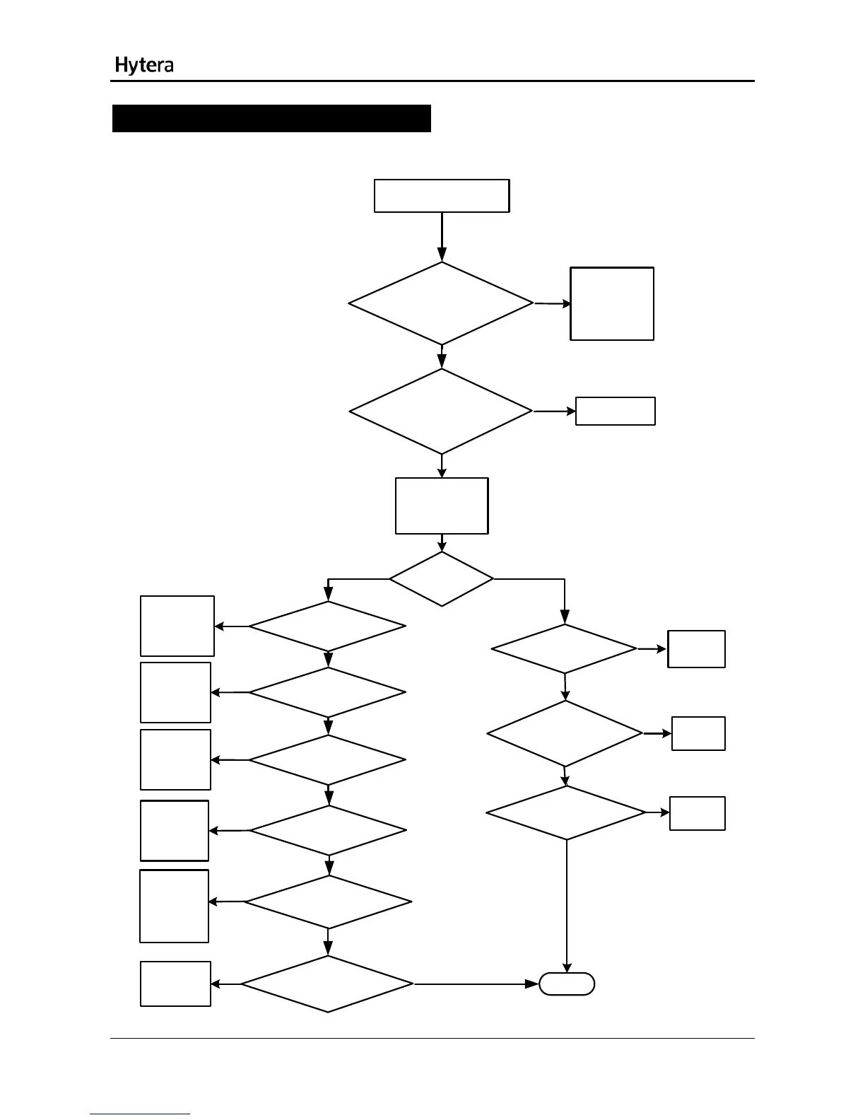
Troubleshooting Flow Chart
TX Circuit
Yes
Abnormal power output
If the current is over
500mA, it indicates
the PA is damaged.
Please replace the
PA (U4102).
Select the test mode and supply 3.7V
voltage. Then check whether the standby
current (240mA) is normal.
No
Yes
Check the TX VCO.
Make the TX VCO locked. Then check
whether the TX VCO outputs stably
[1]
No
Make the TX link in
open-loop working
status.
Check whether the
open-loop transmission
is normal. [2}
Yes
No
Replace
C4139.
Check whether C4139
is soldered inappropriately or
damaged.
Yes
No
Replace the
damaged
parts.
Check whether R4010\
R4011\R4015\C3013\C4014
is soldered inappropriately or
damaged.
Yes
No
Replace the
feedback
balun.
Check whether T4002 is soldered
inappropriately or damaged.
No
Yes
Check whether U4002 outputs
normally. [6]
No
Yes
Replace U4002.
Check whether
U4001 outputs normally. [7]
No
Yes
Check whether
T4001 and the
filter are
soldered
inappropriately
or damaged.
Check whether the input I/Q signal for
U4001 is normal. [8]
Yes
Check the
baseband.
Completed
Check whether the spring
plate for the antenna is assembled
properly. [3]
Check whether U4103 is normal. [4]
Check whether U4102 is supplied
normally. [5]
Re-assemble the
spring plate or
replace it.
Replace U4103.
Replace U4102.
Yes
No
No
No
No
Yes
Yes
Yes
23