Service Manual
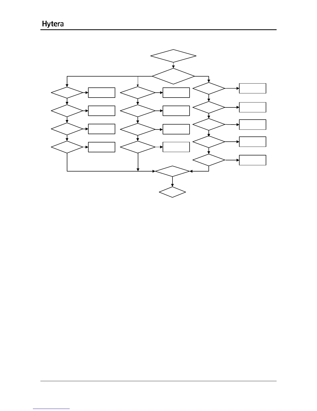
FGU Circuit
CP voltage for TX/RX LO [1]
Check whether
Q6503 is normal. [2]
Check whether
Q6504 is normal. [8]
Check Q6502 and
Q6504.
Check whether
Q1004 is normal.
[4]
Check whether
Q1003 is normal. [4]
Check the varactor. [3]
Check whether
Q1002 is normal. [7]
Check whether
Q1001 is normal. [7]
Check the varactor. [6]
Abnormal FGU
Check whether
Q6502 is normal. [5]
Check U1001. [12]
Check whether
Q1007 is normal. [11]
Check whether
Q1006 is normal. [11]
Check whether
Q1005 is normal. [10]
Check the varactor. [9]
Replace the varactor.
Replace Q1005.
Replace Q1006.
Replace Q1007.
Replace Q1004.
Replace Q1003.
Replace the varactor.
Replace Q6503 and
Q6506.
Replace Q1002.
Replace Q1001.
Replace the varactor.
Replace Q6504 and
Q6506.
Yes
No
Yes
Yes
Yes
Yes
Yes
Yes
Yes
Yes
Yes
Yes
Yes
No
No
No
No
No
No
No
No
No
No
No
No
Yes
Replace U1001.
No
Description:
[1] The CP voltage is 0.5~4.5V.
[2] The voltage at Pin4 of Q6503/Q6506 is 5V.
[3] The varactor is not damaged.
[4] The output voltage by Q1003/Q1004 is 4.8V.
[5] The voltage at Pin4 of Q6502/Q6504 is 5V.
[6] The varactor is not damaged.
[7] The output voltage by Q1001/Q1002 is 4.8V.
[8] The voltage at Pin4 of Q6504/Q6506 is 5V.
[9] The varactor is not damaged.
[10] For Q1005/Q1006, the voltage at the collector is 4.8V; the voltage at the grid is 1.8V; and the
voltage at the emitter is 1.2V.
[11] For Q1007, the voltage at the collector is 4.5V; the voltage at the grid is 0.3V; and the voltage at the
emitter is 0V.
[12] For U1001, the voltage at Pin1 is 3V (i.e. voltage at the R1002 end); the voltage at Pin2 is 5V (i.e.
voltage at the R1004 end); Pin9 provides 12MHz sine signal (amplitude: 0.8V).
27