1
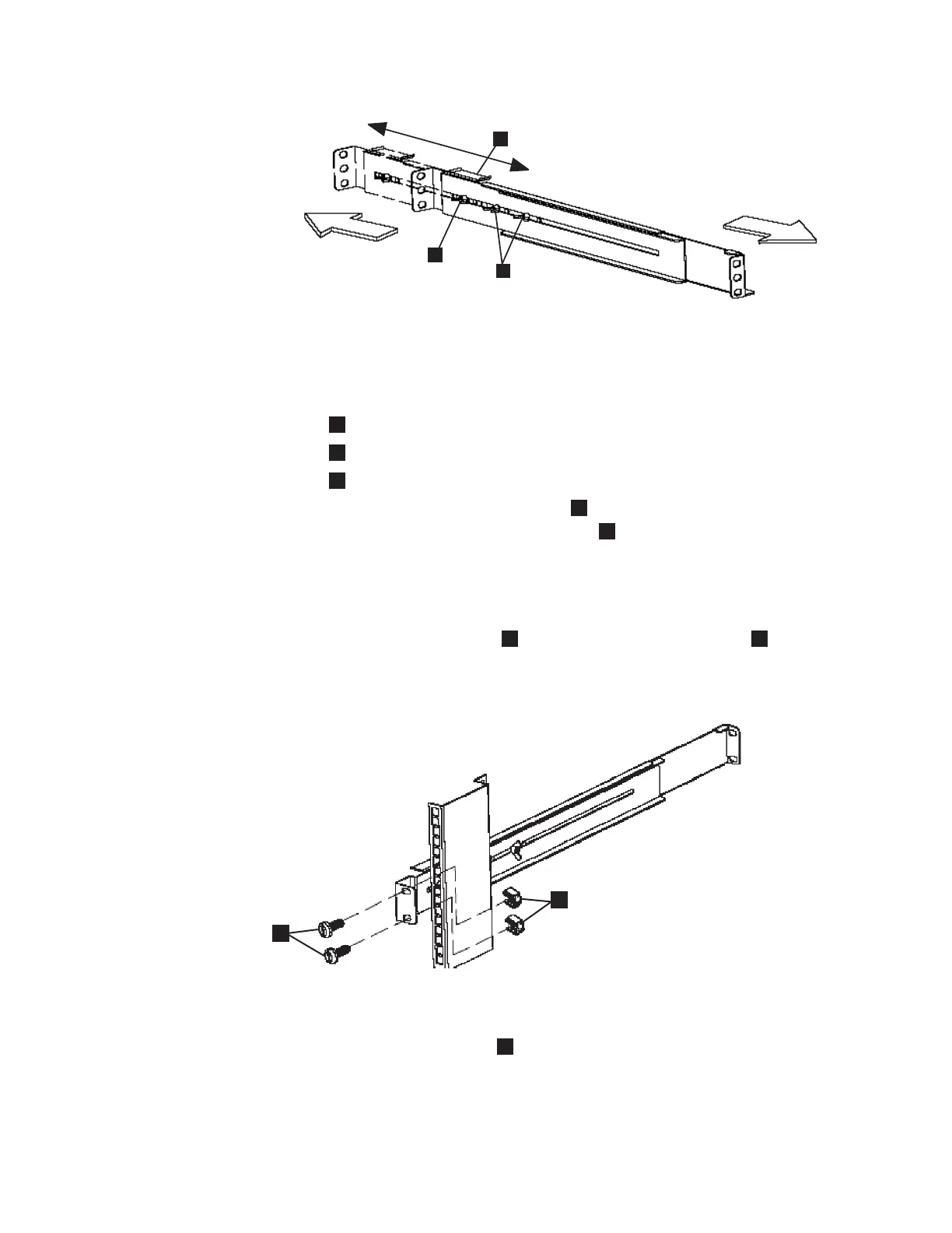
Assembly wing nuts
2
Hold-down bracket
3
Wing nut
5. Position the rear, hold-down bracket (
2
in Figure 50) towards the end of the
rail assemblies and tighten the wing nut (
3
in Figure 50).
6. Select the holes in the rail where you want to position the 2145 UPS-1U.
Note: The bottom flange of the support rail must align with the EIA mark on
the rack.
7. Using two M6 × 10 screws (
1
in Figure 51) and two clip nuts
2
, attach the
rail to the rear of the rack. The customer’s rack might be different than the
one shown here, and if so, might require different clip nuts or fasteners.
8. Attach only the bottom hole of the rail to the front of the rack with one M6 ×
10 screw and one clip nut (
1
in Figure 52 on page 82).
1
2
3
Front
Rear
svc00033
Figure 50. Adjusting the rail depth on the 2145 UPS-1U
1
2
svc00034
Figure 51. Securing the rear rail on the 2145 UPS-1U
Appendix A. SAN Volume Controller 2145-8F4 and SAN Volume Controller 2145-8F2 81

 Loading...


