2. Connect the other end of the Ethernet cable to the proper connector on the
Ethernet hub or switch.
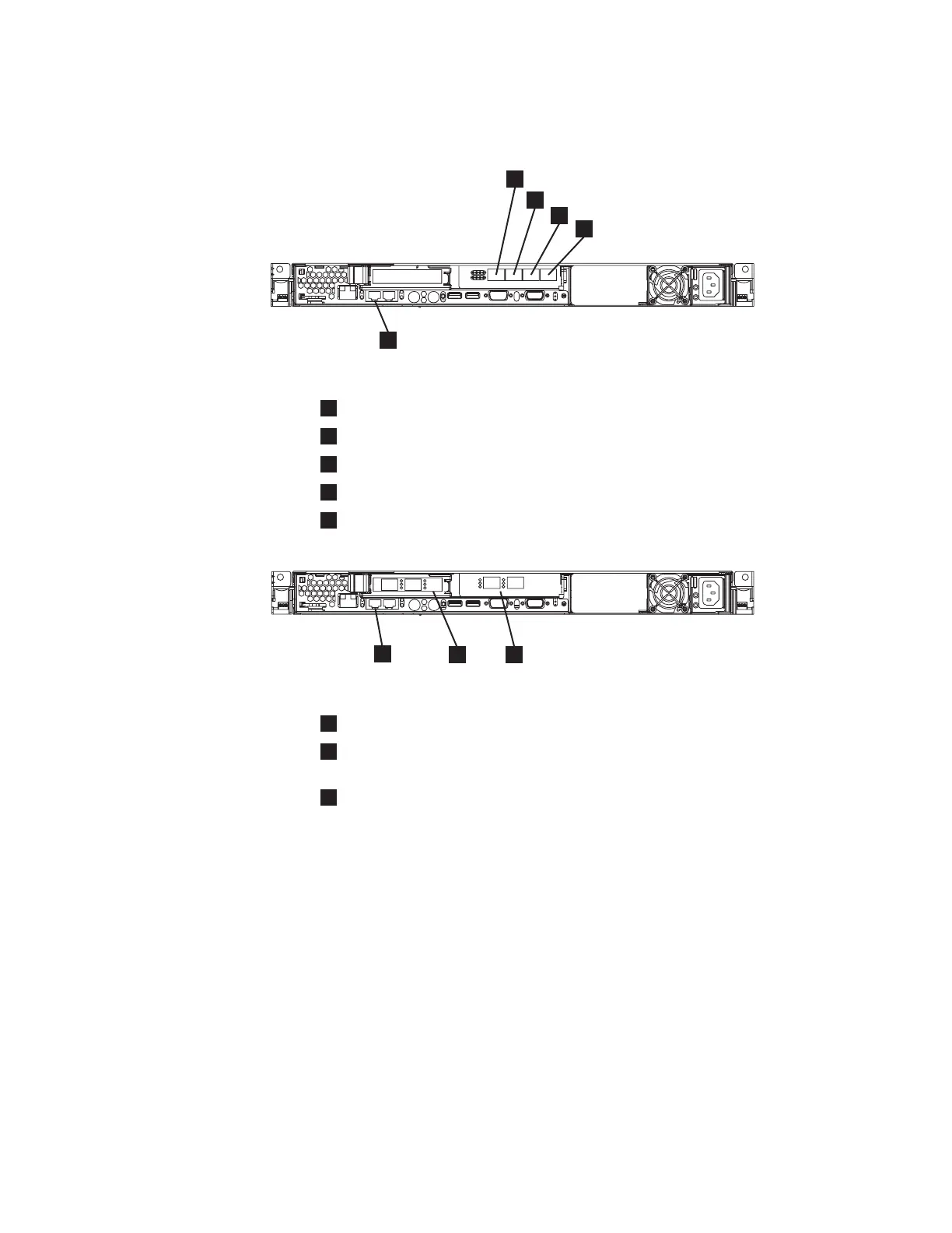
1
Fibre-channel port 1
2
Fibre-channel port 2
3
Fibre-channel port 3
4
Fibre-channel port 4
5
Ethernet port 1
1
Ethernet port 1
2
Low profile duel port fibre-channel host bus adapter (HBA) with ports 1
and 2 (left to right)
3
Full height duel port fibre-channel HBA with ports 3 and 4 (left to right)
Attention: When routing the fibre-channel cables, do not tighten the cable
straps or bend the cables to a radius smaller than 76 mm (3 in.).
3. Connect the fibre-channel cables to the fibre-channel ports as required by the
user’s configuration.
4. Connect the other ends of the fibre-channel cables to the proper connectors of
the fibre-channel switches.
Complete steps 1 on page 94 through 4 for each node that you need to connect to
the SAN and to the Ethernet network.
Verifying the SAN Volume Controller 2145-8F4 or the SAN
Volume Controller 2145-8F2 installation
You must verify the SAN Volume Controller installation after the installation has
completed.
svc00178
1
2
3
4
5
Figure 68. Connectors at the back of the SAN Volume Controller 2145-8F4
svc00090
1
2
3
Figure 69. Connectors at the back of the SAN Volume Controller 2145-8F2
Appendix A. SAN Volume Controller 2145-8F4 and SAN Volume Controller 2145-8F2 95

 Loading...


