4. Remove the protective label from the internal battery connector.
5. Connect the internal battery connector. Each end of the keyed connector has
two wires: one red (+) and one black (−). Join the black wires and the red wires
together.
Note: A small amount of arcing might occur when connecting the batteries.
This is normal and does not damage the unit or present any safety
concerns.
6. Reinstall the front panel. You might need to move the sliding section on the
front of the 2145 UPS-1U to the closed position first.
7. At the back of the 2145 UPS-1U, plug the 2145 UPS-1U main power connector
into the power socket (
1
in the following figure). The 2145 UPS-1U is in
standby mode, so all indicators are off.
It is recommended that each 2145 UPS-1U for an I/O group is connected to a
different power source.
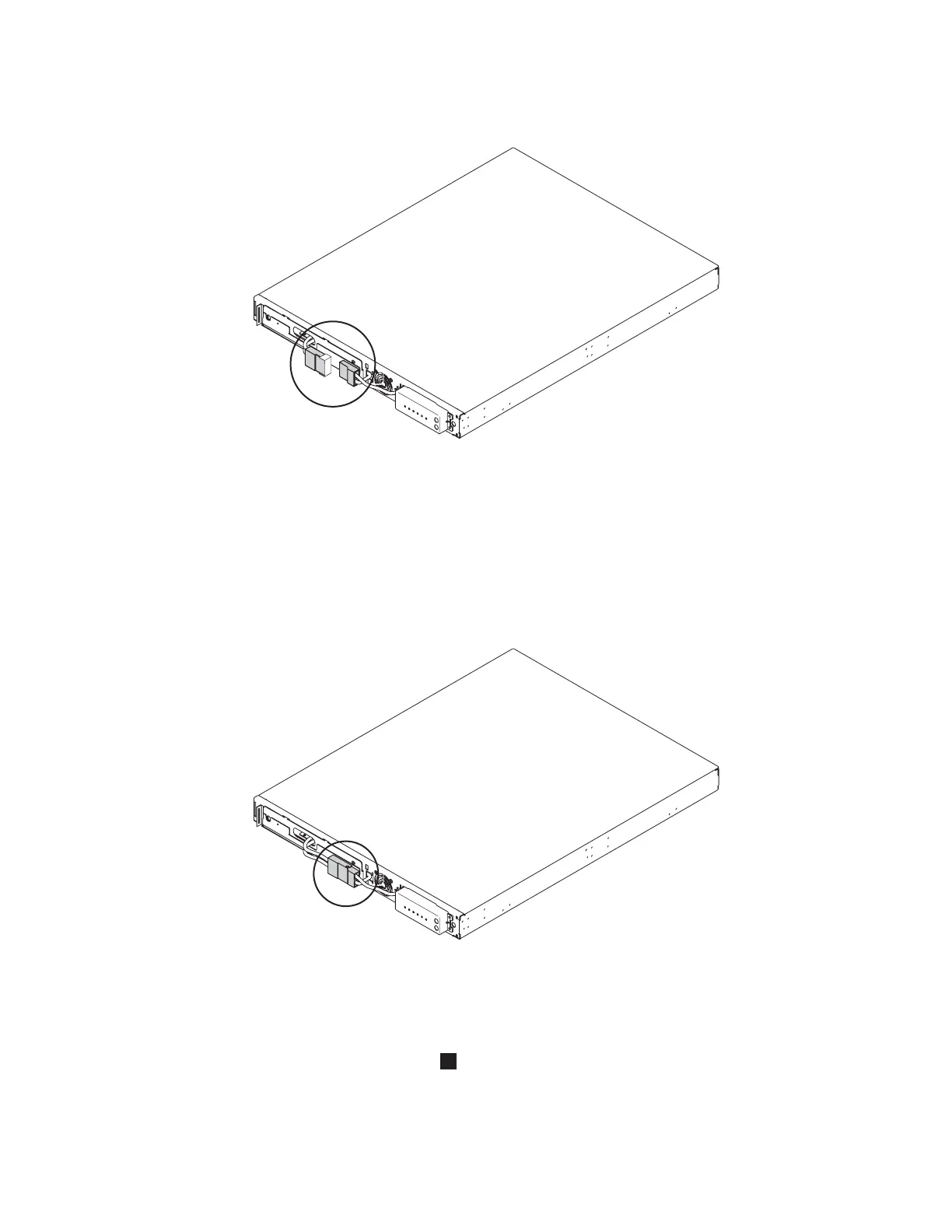
svc00062
Figure 54. The 2145 UPS-1U internal battery connector with protective tape
svc00061
Figure 55. The 2145 UPS-1U internal battery connector
84 IBM System Storage SAN Volume Controller: Hardware Installation Guide
|
|

 Loading...


