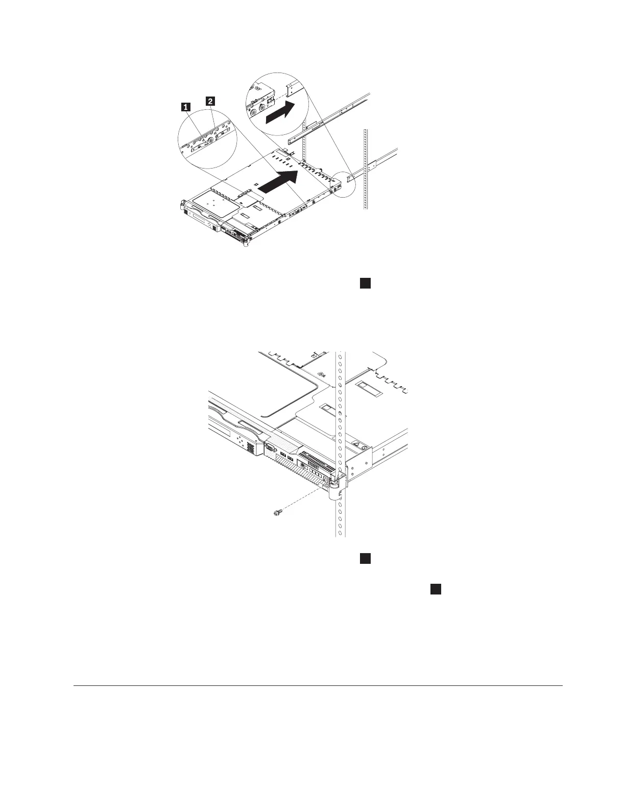
4. Pull the node out of the rack so the slides are fully extended.
5. Press the front slide release latches
1
on both sides of the node and move the
node into the rack cabinet and back out to verify that the node moves freely.
6. Securely tighten the four mounting screws that you previously installed at the
front and rear of both rails.
7. Press the front slide release latches
1
and push the node all the way into the
rack cabinet.
Attention: Use only the rear slide release latches
2
to remove the SAN
Volume Controller 2145-8G4 from the rack.
8. Repeat this procedure for each SAN Volume Controller 2145-8G4 that needs to
be installed.
Tip: If you have available space, leave a 1 space between each node to
improve the air circulation in the rack.
Connecting the SAN Volume Controller 2145-8G4 to the 2145 UPS-1U
Before you connect the SAN Volume Controller 2145-8G4 node to the 2145
uninterruptible power supply-1U (2145 UPS-1U), review the restrictions that exist
between the two systems.
svc00236
svc00229
Chapter 6. Installing the SAN Volume Controller 2145-8G4 hardware 53